Deburring die for numerical control turret punch press

A CNC turret punching machine and mold technology, which is applied in the field of CNC machine tools, can solve the problems of large polishing marks, unfavorable health of operators, and difficulty in unifying manual operations.

Active Publication Date: 2011-11-23
JIANGSU JINFANGYUAN CNC MACHINE CO LTD
View PDF7 Cites 2 Cited by
  • Summary
  • Abstract
  • Description
  • Claims
  • Application Information

AI Technical Summary

Problems solved by technology

[0003] The method of using a polishing machine to remove burrs has the following disadvantages: (1) Compared with punching, the size of the polishing head is too large, so that the actual grinding area of ​​the polishing head is larger when grinding burrs, that is, the remaining polishing marks Larger, which affects the surface quality of the plate; (2) It is difficult to unify the manual operation, and the surface quality after polishing is inconsistent; (3) A large amount of iron filings and grinding powder are produced while grinding burrs, which is not conducive to the health of operators and affects the environment quality

Method used


Image

  • Deburring die for numerical control turret punch press
  • Deburring die for numerical control turret punch press
  • Deburring die for numerical control turret punch press

Examples


Embodiment Construction

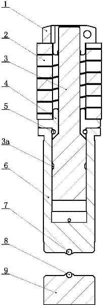
[0013] like figure 1 and figure 2 As shown, the deburring die for the numerical control turret punch of the present invention includes an upper die and a lower die having a common axis; the upper die includes an upper die rod 3, an upper die spring 2, a die nut 1, a spring seat 4 and a guide sleeve 6 , the upper die rod 3 is in the shape of a stepped cylinder with a small upper part and a large lower part, and the middle part of the upper die rod 3 is provided with a conical surface that connects the upper part and the lower part; the die nut 1, the upper die spring 2 and the spring seat 4 are in order from top to bottom. Set on the upper part of the upper die rod 3, the die nut 1 is screwed on the upper end of the upper die rod 3 to compress the upper die spring 2, the lower end of the upper die spring 2 is supported on the convex ring of the spring seat 4, and the lower end of the spring seat 4 The end face is supported on the conical surface in the middle of the upper die...


PUM


Abstract

The invention relates to a deburring die for a numerical control turret punch press. The die comprises an upper die and a lower die, wherein an upper die rod is in a stepped cylinder shape with a small upper part and a large lower part; the middle part of the upper die rod is provided with a conical surface for connecting the upper part with the lower part in a transition mode; a die nut, an upper die spring and a spring seat are sleeved on the upper part of the upper die rod from top to bottom in turn; the die nut is screwed at the upper end of the upper die rod and presses the upper die spring; the lower end of the upper die spring is supported on a convex ring of the spring seat; the lower end face of the spring seat is supported on the conical surface on the middle part of the upper die rod; the lower side of the convex ring of the spring seat is supported on a flange at the upper port of a guide sleeve; the lower part of the upper die rod is inserted into the guide sleeve and canmove up and down along an inner hole of the guide sleeve; an upper ball is embedded in the center of the lower end face of the guide sleeve; the lower die comprises a lower die seat and a lower ball;the lower ball is embedded in the center of the upper end face of the lower die seat; and the upper ball and the lower ball are positioned on the axes of the upper die and the lower die. The die has a high deburring speed, does not generate iron scrap or dust, and can walk along any edge of a punched hole.

Description

technical field [0001] The invention relates to a deburring die for a numerically controlled turret punch, belonging to the technical field of numerically controlled machine tools. Background technique [0002] As a cold working machine tool, CNC turret punching machine mainly performs punching, forming, trimming, small bending, tapping and other work of sheet metal parts. Because there must be a certain gap between the upper and lower molds and the thickness of the plate to ensure the upper mold Exit from the sheet, so there is a certain height of burrs around the lower hole of the sheet after punching. In some working conditions that require high quality of plate processing, it is necessary to remove the burrs on the punched edge. The usual practice is to use a polishing machine to grind off the burrs after the plate is processed. [0003] The method of grinding the burr with a polishing machine has the following shortcomings: (1) Compared with punching, the size of the p...

Claims


Application Information

Patent Timeline
Patent Type & Authority Applications(China)
IPC IPC(8): B21D37/10
Inventor 王其柱佘萍吴宏祥徐长奎芦峰
Owner JIANGSU JINFANGYUAN CNC MACHINE CO LTD
Why Eureka
Try Eureka