
Method and device for forming metal reducer pipe based on laser shock wave technology

A technology of variable diameter pipe and shock wave, which is applied in laser welding equipment, metal processing equipment, welding equipment, etc., can solve the problems of pipe instability, difficulty in adapting, and rupture, and achieve simple and convenient operation, avoid hydraulic equipment, and delay decay Effect

Active Publication Date: 2011-10-26
马鞍山市安工大智能装备技术研究院有限公司
View PDF7 Cites 20 Cited by
  • Summary
  • Abstract
  • Description
  • Claims
  • Application Information

AI Technical Summary

Problems solved by technology

However, when forming, complex hydraulic equipment is required, and the internal pressure and axial load are often difficult to match reasonably, resulting in instability of the pipe after forming, and failure of the pipe fittings such as folding, wrinkling and cracking.
At present, this technology is limited to the forming of pipe fittings of materials with low yield strength such as aluminum alloy and stainless steel, and it is difficult to adapt to the forming of pipe fittings of titanium alloys with high yield strength.

Method used


Image

  • Method and device for forming metal reducer pipe based on laser shock wave technology
  • Method and device for forming metal reducer pipe based on laser shock wave technology
  • Method and device for forming metal reducer pipe based on laser shock wave technology

Examples


Embodiment Construction

[0019] The details and working conditions of the specific device proposed by the present invention will be described in detail below in conjunction with the accompanying drawings.

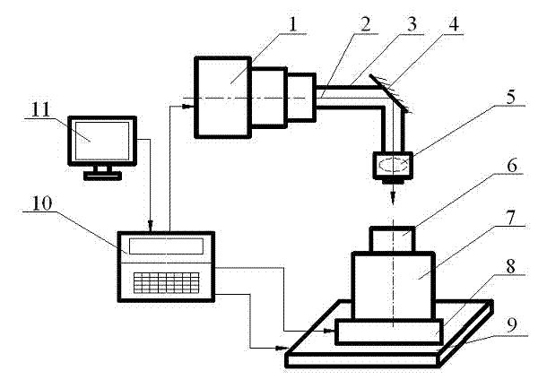
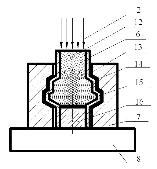
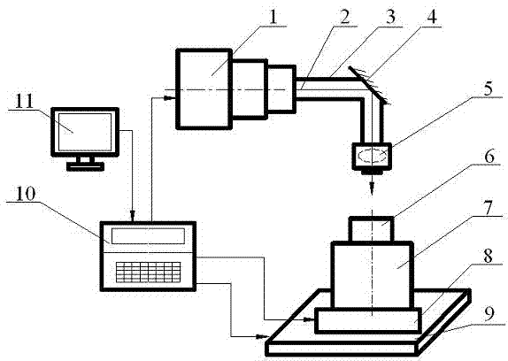
[0020] The device mainly includes a laser generator 1, a light guide system, a workpiece fixture system and a control system. Wherein the light guide system includes a light guide pipe 3 , a total reflection mirror 4 and an impact head 5 . The workpiece fixture system consists of a metal reducer tube blank 6, a protective pad 14, a split mold 7, a constraining layer (water) 12, an absorption layer (black paint) 15, a blocking rod 16, a bracket 8, and a workbench 9. The control system includes a computer 11 and a controller 10 .

[0021] The laser generator 1 emits an optimized laser pulse beam 2 , the beam mode of the laser pulse beam 2 can be multiple modes such as fundamental mode and multi-mode, which are regulated and controlled by the controller 10 . The laser pulse beam 2 emitted by the las...


PUM


Abstract

The invention discloses a method and device for forming a metal reducer pipe based on a laser shock wave technology and belongs to the technical field of laser processing. In the invention, the upper end part, separated from a pipe fitting, of a plugging rod is coated with a laser energy absorption layer; a laser beam enters the interior of a pipe billet to be formed along the axis of the pipe billet, thereby irradiating on the absorption layer on the upper end part of the plugging rod; the absorption layer absorbs laser energy so as to be gasified and ionized, thus forming high-voltage plasmas; and the high-voltage plasmas quickly expand to form a high-amplitude shock wave, thereby promoting the expansion of the pipe billet until the pipe billet is jointed with the profile of a mould, therefore the deformed shape of the pipe billet is in accordance with the profile of the mould. In the invention, the laser shock wave controlled in parameter is utilized as a power source for internal high pressure forming of the pipe billet, and good safety is provided; and the method and device provided by the invention are suitable for not only forming the pipe billet of a material extremely low in yield limit, but also forming the pipe billet with high yield strength; besides, continuous multi-pulse laser irradiation can be performed and uninterrupted multi-impact can be carried out; and high production efficiency is ensured.

Description

technical field [0001] The invention belongs to the technical field of laser processing, and relates to a method and a device for forming a metal reducing tube based on laser shock wave technology. Background technique [0002] As a functional element in the pipeline system, an elastic deformation compensation element, and a transition joint for connecting different pipe fittings, the reducing pipe is widely used in the fields of aviation, aerospace, and automobiles. The commonly used processing methods include: segmental stamping and welding, Explosive forming and internal high pressure hydraulic forming. [0003] Segmental stamping and welding is currently the most commonly used processing method for variable diameter pipes. It first divides the variable cross-section pipe fittings designed in the drawing into several different parts according to the diameter and changing trend, and then performs different parts for different parts. Stamping and forming, and finally the p...

Claims


Application Information

Patent Timeline
IPC IPC(8): B23K26/00B23K26/18B23K26/42B23K26/70
Inventor 张兴权左立生于庆丽余晓流张俊何广德王海荣石宝玉
Owner 马鞍山市安工大智能装备技术研究院有限公司
Learn More