
Bottom lifting type resistance heating annealing furnace

A resistance heating, lifting technology, applied in the field of annealing furnace, can solve the problem of high scrap rate, achieve a high degree of automation and meet the needs of heat treatment

Inactive Publication Date: 2011-10-19
重庆飞达电炉有限公司
View PDF3 Cites 17 Cited by
  • Summary
  • Abstract
  • Description
  • Claims
  • Application Information

AI Technical Summary

Problems solved by technology

[0004] The present invention is aimed at the annealing furnace of the prior art, which cannot meet the actual needs in terms of heating efficiency, furnace temperature uniformity, furnace temperature stability, cooling rate, and processing capacity of each furnace when processing some special workpieces, resulting in scrap rate Insufficiencies such as extremely high, provide a bottom lifting resistance heating annealing furnace with high degree of automation, high furnace temperature uniformity, and strong furnace temperature stability

Method used


Image

  • Bottom lifting type resistance heating annealing furnace
  • Bottom lifting type resistance heating annealing furnace
  • Bottom lifting type resistance heating annealing furnace

Examples


Embodiment Construction

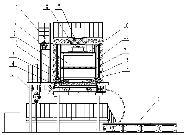
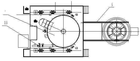
[0019] The bottom lifting type resistance heating annealing furnace of the present invention includes a furnace body 1, a furnace hearth 2 and a control device. The furnace body 1 is composed of a metal furnace shell on the surface and a heat-resistant furnace lining inside, and the cavity inside the furnace body 1 forms a furnace hearth 2 , as the area where the workpiece to be heat treated is placed; the bottom surface of the furnace body 1 is a furnace bottom cover 3 that is movable. The track 5 cooperates and can move on the track 5 (under the action of the self-contained or external driving device); the furnace bottom cover 3 can rise or fall under the drive of the lifting device 6, and after rising, it can be sealed with the furnace body 1 (sealed furnace The furnace mouth on the bottom surface of the body 1) forms the working bottom surface of the furnace 2, falls on the matching track 5 after falling, and moves on the track 5 through the running wheel 4. In the figure,...


PUM


Abstract

The invention discloses a bottom lifting type resistance heating annealing furnace comprising a furnace body, a furnace cavity and a control device. A movable furnace bottom cover is arranged on the bottom surface of the furnace body, travelling wheels are arranged below the furnace bottom cover, the furnace bottom can be lifted under the driving of a lifting device, after being lifted, the furnace bottom cover is closely matched wit the furnace body so as to form a work bottom surface of the furnace cavity, and being descended, the furnace bottom cover drops on a matched track, and the travelling wheels can move on the track; a plurality of electric heaters are arranged on the side surface of the furnace cavity; a fan, the top guide plate and a side guide plate are arranged on the top end of the furnace cavity, a certain gaps is arranged between the side guide plate and the electric heater so as to form an air circulation channel, a cooling air channel is arranged on the furnace body, and used for sending cooling air into the furnace cavity. For the annealing furnace, the degree of automation is high; the processes such as loading, travelling, lifting of movable furnace bottom, heating for temperature rising, temperature reducing and the like are conducted under the control of the control device, and the degree of automation is high; and in the heating process, the annealing furnace achieves the demands that the furnace temperature uniformity is higher, the furnace temperature stability is higher, and the temperature reducing rate can meet the thermal treatment process.

Description

technical field [0001] The invention relates to an annealing furnace for heat-treating workpieces, in particular to a bottom-lift resistance heating annealing furnace for heat-treating special glass. Background technique [0002] In order to improve the performance of the workpiece, heat treatment under various temperature conditions is used in the prior art to improve [0003] The internal structure of the workpiece, surface hardness, stress relief, etc., so that the mechanical indicators of the workpiece can meet the process requirements. The annealing furnaces in the prior art generally have the function of heating up and heating up to the temperature required by the process under the control of the control device. However, when the temperature is lowered, it is generally cooled with the furnace, etc., and the slope of the temperature drop cannot be accurately controlled, and the temperature rise cannot be satisfied. And the heat treatment requirements of workpieces th...

Claims


Application Information

Patent Timeline
IPC IPC(8): C03B25/00
Inventor 李大河
Owner 重庆飞达电炉有限公司
Learn More