
Method for arranging film sensor on alloy substrate

A thin-film sensor and composite substrate technology, which is applied in the direction of superimposed layer plating, metal material coating process, coating, etc., can solve the problems of difficult bonding, non-uniform covering surface, non-uniform insulating layer, etc., and achieve improved Effects of joint strength, reduced thickness requirements and difficulty of fabrication

Inactive Publication Date: 2012-11-07
UNIV OF ELECTRONICS SCI & TECH OF CHINA
View PDF1 Cites 2 Cited by
  • Summary
  • Abstract
  • Description
  • Claims
  • Application Information

AI Technical Summary

Problems solved by technology

In the preparation process of this kind of thin film sensor, there are the following defects: one is to make the NiCrAlY transition layer and Al 2 o 3 There is good adhesion between the insulating layers. The Al layer precipitated on the surface of NiCrAlY must be 1-2 μm thick and required to be evenly distributed on the surface of the transition layer. To achieve the required thickness and requirements of the Al layer precipitation, it is necessary to The thickness of the NiCrAlY layer is more than 100 μm, which is extremely difficult in terms of the preparation of the transition layer and the bonding force between the transition layer and the substrate that needs to be achieved in the subsequent high-temperature heat treatment process; the second is the transition from NiCrAlY The layer-precipitated Al is usually distributed in an island shape, rather than uniformly covering the surface, so that in the process of thermal oxidation of the precipitated Al, the surface will not only form Al 2 o 3 In addition, there will be oxides with a loose structure such as nickel oxide, which will affect the subsequent evaporation of the transition layer Al 2 o 3 The quality of the device and the structure of the device have adverse effects, especially in the high temperature working environment of more than 800 °C, due to the different thermal expansion coefficients (coefficients) of Al 2 o 3 The shedding of the insulating layer, which leads to the failure of the thin film sensor and other disadvantages

Method used

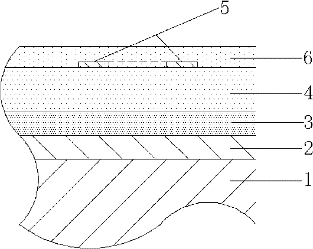

Image

  • Method for arranging film sensor on alloy substrate

Examples


Embodiment Construction

[0017] Take a nickel (Ni)-based alloy plate as the alloy substrate 1 to be tested, and prepare a K-type NiCr-NiSi thermocouple film sensor on it as an example:

[0018] A. Surface treatment of the alloy substrate: a nickel (Ni)-based alloy plate of (length × width × thickness) 30 × 95 × 5mm is used as the alloy substrate 1 to be tested, and the surface of the alloy substrate to be tested is treated with acetone and ethanol first and then Cleaning, drying under nitrogen atmosphere after cleaning;

[0019] B. Deposit a NiCrAlY alloy transition layer on the alloy substrate: place the cleaned Ni-based alloy substrate 1 in a vacuum of 6.0×10 -4 In a vacuum (back vacuum) environment of pa, NiCrAlY alloy is used as the target material, and argon gas with a purity of 99.999% (volume percentage) is input as the sputtering medium. ) is under the condition of 0.5Pa, the NiCrAlY alloy is deposited on the Ni-based alloy substrate 1 by the DC magnetron sputtering method, and the deposition...


PUM

PropertyMeasurementUnit
thicknessaaaaaaaaaa
thicknessaaaaaaaaaa
electrical resistanceaaaaaaaaaa

Abstract

The invention discloses a method for producing a film sensor by using a turbine engine blade to be detected or the like as a substrate in the field of film sensors. The method comprises the following steps of: treating the surface of an alloy substrate, depositing a NiCrAlY alloy transition layer on the alloy substrate, separating out metallic aluminum, sputtering a metallic aluminum layer, performing oxidation treatment, setting an Al2O3 ceramic insulating layer, and setting a functional layer and an Al2O3 protective layer of the film sensor. A layer of metallic aluminum is directly sputtered after the aluminum of certain thickness is separated out of the NiCrAlY layer, and the separated aluminum and the sputtered aluminum are uniformly distributed on the surface of the NiCrAlY transition layer and then oxidized to generate an Al2O3 connecting transition layer; and the thickness of the NiCrAlY layer is only about 1 / 20 of the background technology. Therefore, the method has the characteristics that: the NiCrAlY transition layer is thin, the connecting strength of the NiCrAlY transition layer and the Al2O3 ceramic insulating layer is high, the preparation difficulty and the production cost are low, and the method is safe and reliable during working in the environment of about 1,000 DEG C and can provide accurate and reliable design proof for research and design of a turbine engine and the like.

Description

technical field [0001] The invention belongs to the technical field of thin-film sensor design and production, in particular to a method of using the turbine engine blade to be measured, the inner wall of the combustion chamber, etc. as an alloy substrate, and directly setting a thin-film sensor on the surface of the turbine engine blade to be measured, the inner wall of the combustion chamber, etc. , this type of thermocouple can be widely used to measure the surface temperature distribution of turbine engine blades, combustion chambers, etc., and provide corresponding and more accurate basic data for the research and design of turbine engines. Background technique [0002] When modern aero-engines are working, because the turbine blades and combustion chamber are in the harsh environment of high temperature and high pressure generated by gas combustion, the surface temperature of the turbine blades and combustion chamber rises sharply, and at the same time a large thermal s...

Claims


Application Information

Patent Timeline
Patent Type & Authority Patents(China)
IPC IPC(8): C23C28/00
Inventor 蒋洪川陈寅之刘治君李瑶张万里刘兴钊李言荣
Owner UNIV OF ELECTRONICS SCI & TECH OF CHINA
Learn More