Radiating fin

A technology of heat sinks and heat dissipation fins, applied in cooling/ventilation/heating transformation, electrical components, electrical solid devices, etc. Simple and stable, improved heat dissipation performance, obvious effect of heat dissipation

Inactive Publication Date: 2011-09-14
TAICANG XINGGANG METAL MATERIAL
View PDF6 Cites 5 Cited by
  • Summary
  • Abstract
  • Description
  • Claims
  • Application Information

AI Technical Summary

Problems solved by technology

[0003] The heat dissipation fins are connected to the base by welding to increase the weight of the heat sink, and there is often a gap between the base and the heat dissipation fins, which affects the thermal conductivity;
[0004] Using the snap-in method, there are several slots on the upper surface of the base, and the cooling fins are inserted into the slots, and are engaged with the slots. In this way, there is also a gap between the base and the cooling fins. , which affects the heat transfer between the cooling fins and the base member, resulting in poor cooling effect;
[0005] In order to avoid gaps between the base and the heat dissipation fins, the heat dissipation fins can also be fixedly connected to the base by means of glue, and the combination of the two is relatively tight, so that no gaps will be generated; although this method solves the aforementioned problem The problem, however, is that the adhesive connection method cannot make the base and the heat dissipation fins firmly combined, and the heat dissipation fins will fall off from the base. In addition, the heat conduction effect of the glue is poor, which will have a certain impact on the heat dissipation effect

Method used


Image

  • Radiating fin
  • Radiating fin

Examples


Embodiment Construction

[0014] The present invention will be further described in detail below with reference to the accompanying drawings and embodiments, and it should be understood that these embodiments are only used to illustrate the present invention and not to limit the scope of the present invention.

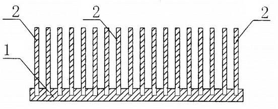
[0015] like figure 1 As shown, the heat sink includes a base 1 and a set of heat dissipation fins 2, the base 1 and the heat dissipation fins 2 are made of aluminum alloy materials with good thermal conductivity, and the heat dissipation fins 2 are punched by stamping Insert the base 1 and connect it firmly; due to punching, the upper surface of the base 1 and the heat dissipation fin 2 and the bottom surface of the base 1 will have depressions and protrusions respectively, and the protrusions can be punched or It is removed by grinding to maintain the flatness of the bottom surface, so that the base 1 is closely attached to the heat source, and the heat dissipation area is enlarged.

[0016] ...


PUM


Abstract

The invention discloses a radiating fin comprising a substrate and a group of radiating fins, wherein the radiating fins are inserted into the substrate in a stamping mode and fixedly connected with the substrate; the space between adjacent radiating fins ranges from 3mm to 6mm; and the thickness of each radiating fin ranges from 5mm to 20mm, and the height range from 30mm to 250mm. The radiating fin enables the substrate and the radiating fins to be fixedly connected in the stamping mode, is simple in structure, stable and fully-fit in connection, sufficient in heat conduction and obvious in radiating effect, and does not have gaps, and the substrate and the radiating fins are made of aluminium alloy having good heat-conducting property, thus greatly improving the heat dispersion.

Description

technical field [0001] The present invention relates to a heat sink. Background technique [0002] With the continuous development of science and technology, new products are constantly being introduced in the fields of computers and machinery manufacturing. These products often require the use of heat sinks. The current heat sinks mainly include bases and heat sink fins, which are commonly welded, snap-connected and glued. Glue connection method. [0003] Connecting the heat dissipation fins and the base by welding increases the weight of the heat dissipation fins, and there is often a gap between the base and the heat dissipation fins, which affects the thermal conductivity; [0004] In the way of clamping, there are several slots on the upper surface of the base, and the heat dissipation fins are inserted into the slots, and are mutually clamped with the slots. In this way, there is also a gap between the base and the heat dissipation fins. , which affects the heat tran...

Claims


Application Information

Patent Timeline
Patent Type & Authority Applications(China)
IPC IPC(8): H01L23/367H05K7/20
Inventor 徐长荣顾仕娣林勇翔
Owner TAICANG XINGGANG METAL MATERIAL
Why Eureka
Try Eureka