Method for manufacturing buoy of air valve of hydroelectric generating unit

The technology of a hydroelectric unit and its production method is applied in the field of production of mixed-flow generator unit components in power plants. It can solve problems such as failure to use the original process, unsuitable finished products, and large welding deformation, so as to solve the problem of buoy corrosion and ensure long-term normal operation. smooth surface effect

Active Publication Date: 2011-08-31
YUNFENG POWER PLANT
View PDF4 Cites 0 Cited by
  • Summary
  • Abstract
  • Description
  • Claims
  • Application Information

AI Technical Summary

Problems solved by technology

Due to the humid working environment and wear and tear of the equipment, the air valve buoy stays in the water for a long time, and a large area of ​​corrosion occurs on the surface of the buoy, causing the gap between the buoy and the pipe wall to be too narrow. discharge, resulting in the failure of the air valve action, causing the main valve to appear dynamic water opening phenomenon, which has caused important safety hazards to the normal and safe operation of the main valve
In order to solve the shortcoming that the buoy is easy to rust, it is necessary to change the material of the buoy, and use stainless steel
Due to the special structure of the buoy, there is no current product in the market, and the production cost is relatively high according to the original process, and it is not suitable for finished products
If stainless steel is used, the rust can be solved, but the welding deformation is relatively large, so the original process cannot be used, and a new process must be used to produce qualified products

Method used


Image

  • Method for manufacturing buoy of air valve of hydroelectric generating unit
  • Method for manufacturing buoy of air valve of hydroelectric generating unit
  • Method for manufacturing buoy of air valve of hydroelectric generating unit

Examples


Embodiment Construction

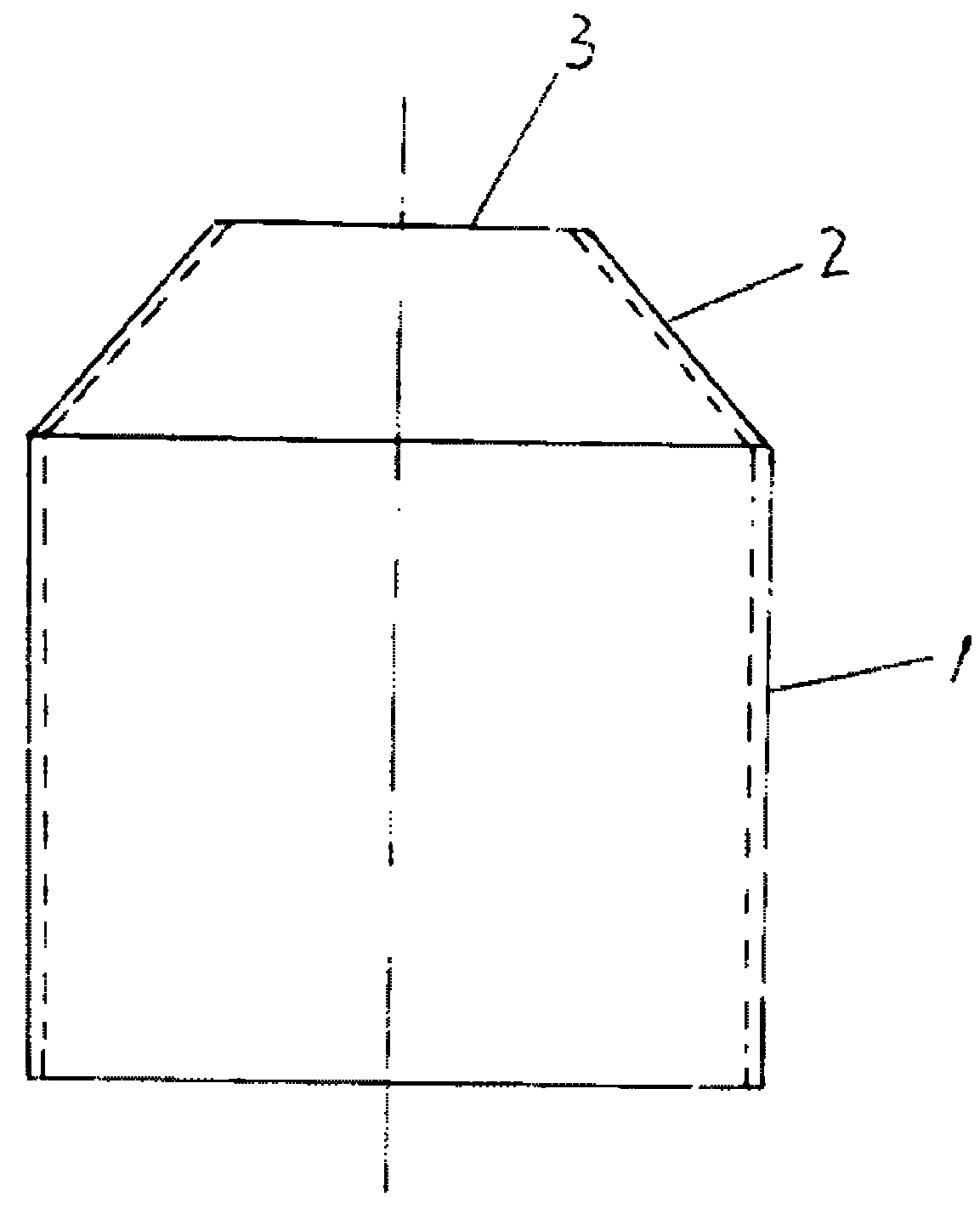
[0015] see figure 1 , the air valve buoy is a cylindrical structure in which a circular tube 1 (or called a cylinder) and a tapered tube 2 are connected as one. The upper part has an opening 3. It consists of a Φ600mm, wall thickness 10mm, 300mm long circular tube 1 and a 147mm long tube. , Bottom Φ600, top Φ280 conical tube 2 welded.

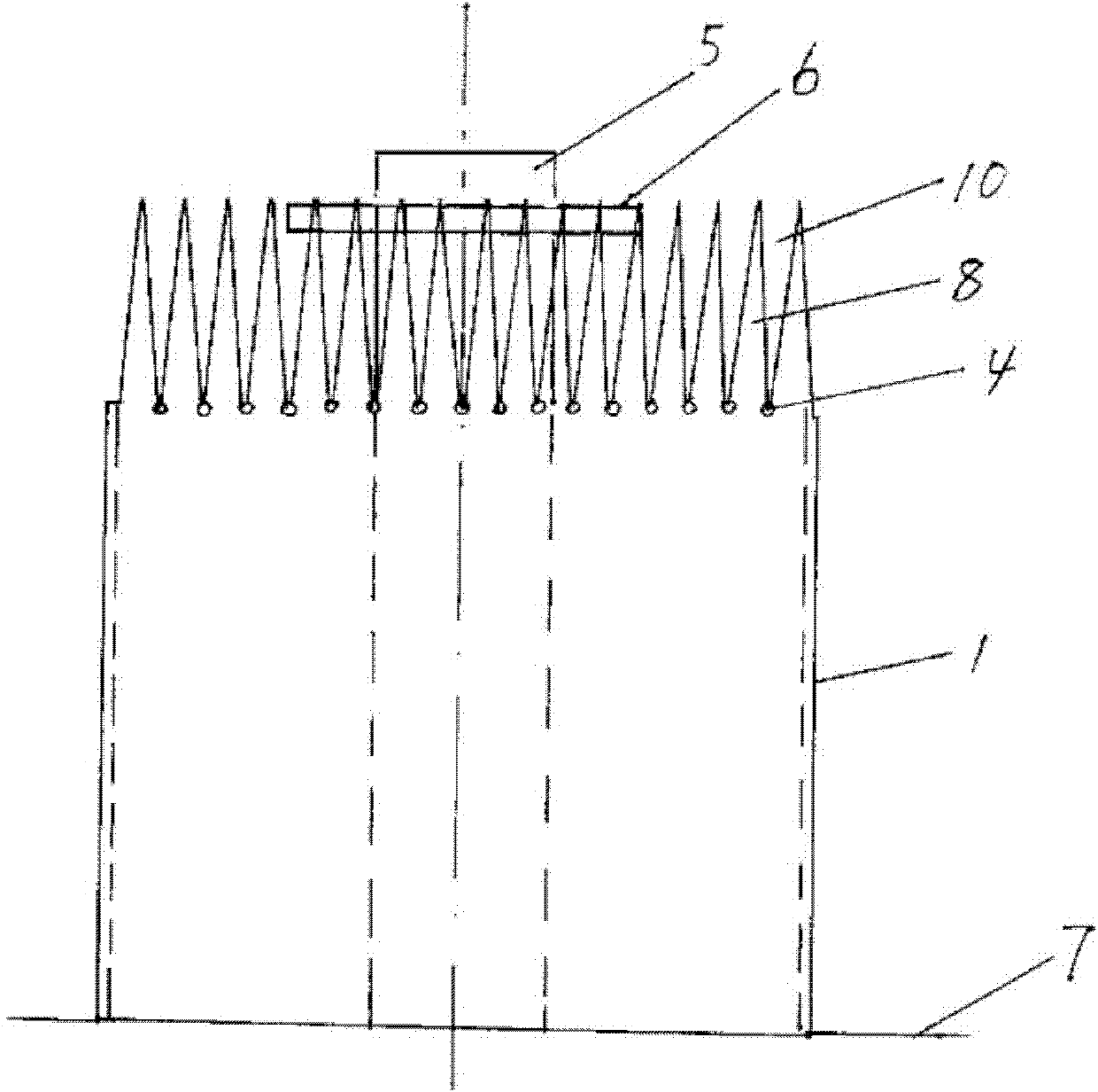
[0016] see figure 2 , 3 , the manufacturing method of the hydroelectric unit air valve buoy comprises the following steps:

[0017] 1. Purchasing a Φ600 stainless steel pipe with a wall thickness of 10mm according to the drawing of the air valve, and cutting a section of round pipe with a height of 447mm.

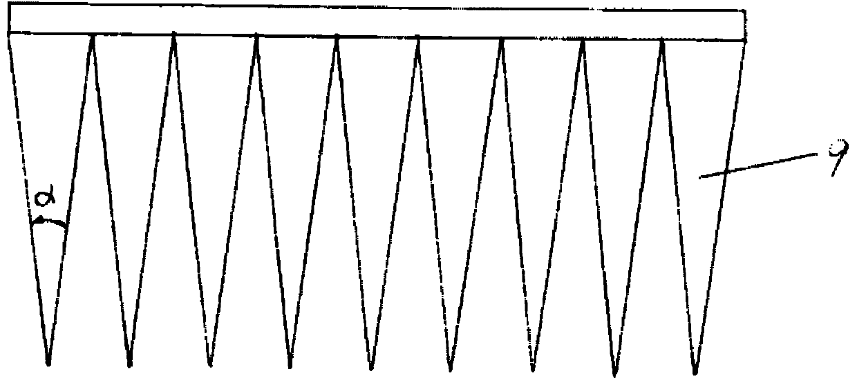
[0018] 2. To make a variable-diameter sample, expand the soft plastic plate with a length of 1884mm (equal to the circumference of a Φ600 round tube) and a width of 220mm (see figure 2 ). There are 24 triangles 9 in total, and the cone angle α is 15°. The height of triangle 9 is 198mm (equal to the hypotenuse length of 2 sections of ...


PUM

PropertyMeasurementUnit
angleaaaaaaaaaa

Abstract

The invention relates to a method for manufacturing components of a mixed flow type generating set in a power plant, namely a method for manufacturing a buoy of an air valve of a hydroelectric generating unit. The method comprises the following steps of: taking a stainless steel tube of which the diameter is equal to that of the buoy, wherein the length of the stainless steel tube is equal to thesum of the height of a round tube section of the buoy and the length of a beveled edge of a tapered section; drawing triangles side by side from the upper end to the lower end on the circumferential surface of the stainless steel tube; cutting an inverted triangle in a stripping way to obtain a spaced rack shape, and treating by using an angle grinder; vertically welding a central rod of which the upper end is provided with a central disc to a flat base steel plate and sleeving the stainless steel tube on the central rod and the central disc, wherein the diameter of the central disc is equal to that of an upper opening of the buoy and the height of the central disc is equal to that of the buoy; and heating racks through gas welding, bending the racks on the central disc in turn, performing spot welding among the racks through electric welding, taking down the stainless steel tube, connecting the racks through electric welding, and polishing to form the buoy with the upper opening. Themethod has the characteristics that: the buoy is reasonable in process, hard to rust and long in service life, and normal work of a main valve is guaranteed.

Description

technical field [0001] The invention relates to a method for manufacturing a part of a mixed-flow generating set in a power plant, that is, a method for manufacturing an air valve buoy of a hydroelectric set. Background technique [0002] In the prior art, the mixed-flow generating sets adopted in the power plant are provided with a main valve separately, and two air valves are arranged behind the main valve. The main function of the air valve is: when the main valve is opened, the air in the pressure steel pipe and the volute is removed to ensure that the main valve is opened in still water; Steel pipe and volute will not be damaged. Therefore, the operation reliability of the air valve will directly affect the safe and stable operation of the unit. The action principle of the air valve is: when the main valve is closed, the valve is opened by the weight of the buoy to supply air; when the main valve is opened, with the rise of the water level, the buoyancy on the buoy is...

Claims


Application Information

Patent Timeline
Patent Type & Authority Applications(China)
IPC IPC(8): B23P15/00
Inventor 程兴智刘春生
Owner YUNFENG POWER PLANT
Why Eureka
Try Eureka