Multi-wavelength micro illumination device
What is Al technical title?
Al technical title is built by PatSnap Al team. It summarizes the technical point description of the patent document.
A lighting device and light beam technology, applied in microscopes, optics, instruments, etc., can solve the problems of multiple pulse lasers out of synchronization, limited number of wavelengths, low energy density, damage, etc., to overcome sample degeneration or even damage, and overcome the number of wavelengths Limited, overcoming desynchronization effects
Active Publication Date: 2012-05-30
INNOVATIVE SEMICON SUBSTRATE TECH CO LTD
View PDF0 Cites 1 Cited by
Summary
Abstract
Description
Claims
Application Information
AI Technical Summary
This helps you quickly interpret patents by identifying the three key elements:
Problems solved by technology
Method used
Benefits of technology
Problems solved by technology
[0003] The purpose of the present invention is to provide a multi-wavelength micro-illumination device; in the device, multiple excitation wavelengths are simultaneously provided by the same pulse laser, which overcomes the shortcoming of low energy density of non-laser light sources and overcomes the need for synchronization of multiple pulse lasers. The shortcomings of misalignment and limited number of wavelengths overcome the shortcomings of low energy density of continuous output lasers and sample denaturation or even damage caused by continuous excitation of samples
Method used
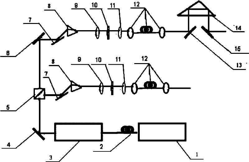
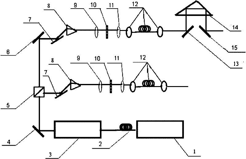
Image
Click on the blue label to locate the original text in one second.
Reading with bidirectional positioning of images and text.
Examples
Embodiment 1
[0016] Embodiment 1, micro-illumination device
[0017] In the microscopic illumination device provided by the present invention, the laser light source output by the picosecond pulse laser 1 is incident on the nonlinear photonic crystal fiber 2 to obtain a broadband laser light source; the pulse laser output by the broadband laser light source is incident on the acousto-optic modulator 3 Above, the repetition frequency of the output laser pulse can be controlled by controlling the repetition frequency of the radio frequency pulse of the acousto-optic modulator 3, and a laser pulse beam with a suitable repetition frequency is obtained; the laser beam is coupled into the beam splitter 5 through the mirror 4 to obtain Two parallel output beams; each output beam is coupled into a wavelength selector through a reflector 7, and the wavelength selector is composed of a dispersion prism 8, a lens a9, a spatial light modulator 10, and a lens b11, and the wavelength selector is used to ...
PUM
Property
Measurement
Unit
diameter
aaaaa
aaaaa
Abstract
The invention provides a multi-wavelength micro illumination device. In the device, a laser pulse output by a picosecond pulse laser or a femtosecond pulse laser is incident to a nonlinear photonic crystal fiber to obtain a broadband laser source; the pulsed laser beam output by the broadband laser source is incident to an acoustooptical modulator to obtain a laser pulse beam with a repetition frequency; a beam splitter and a plurality of reflectors are arranged on the optical path of the laser pulse beam; the laser pulse beam is divided into n parallel output beams (n is a natural number equal to or larger than 2); a dispersion prism or a diffraction grating, a lens (a), a spatial light modulator and a lens (b) are sequentially arranged on the optical path of each output beam; and (n-1) output beams respectively pass through a right angle prism after passing through the dispersion prism or the diffraction grating, the lens (a), the spatial light modulator and the lens (b) to obtain nparallel output beams with different delay time. The multi-wavelength micro illumination device provided by the invention can provide laser wavelengths with a wide waveband range from near ultraviolet to mid-infrared and high spectral energy density above 1 nJ / nm, and is suitable for excitation of the most of fluorescence and Raman samples. Additionally, the plurality of laser wavelengths are from the same laser source so as to obviate the problem of synchronous time maladjustment, and the apparatus cost can be reduced greatly by using one pulse laser.
Description
technical field [0001] The invention relates to a multi-wavelength microscopic illumination device, which belongs to the field of optical microscopic imaging. Background technique [0002] With its non-invasive three-dimensional imaging capability, optical microscopic imaging still accounts for about 80% of life science imaging research (Stefan W. Hell, et al., Science, 316, 25 (2007)). With the development of optical microscopy imaging technology, multicolor excitation fluorescence microscopy (Amit Agrawal, et al., PNAS, 105, 9, 3298-3303 (2008)), stimulated radiation depletion super-resolution microscopy (Thomas A .Klar, et.al., Physical review E., 64, 066613(2001); Marcus Dyba, et.al., Phys.Rev.Lett., 88(16), 163901(2002)), and coherent inverse Stokes Raman scattering microscopy (Andreas Zumbusch, et. al., Phys. Rev. Lett., 82, 20, 4142-4145 (1999)), etc. All these microscopic imaging techniques require multi-wavelength excitation. The traditional multi-wavelength excit...
Claims
Application Information
Patent Timeline
Application Date:The date an application was filed.
Publication Date:The date a patent or application was officially published.
First Publication Date:The earliest publication date of a patent with the same application number.
Issue Date:Publication date of the patent grant document.
PCT Entry Date:The Entry date of PCT National Phase.
Estimated Expiry Date:The statutory expiry date of a patent right according to the Patent Law, and it is the longest term of protection that the patent right can achieve without the termination of the patent right due to other reasons(Term extension factor has been taken into account ).
Invalid Date:Actual expiry date is based on effective date or publication date of legal transaction data of invalid patent.