Charge pump circuit in charge pump phase-locking loop

A technology of charge pump and phase-locked loop, applied in the direction of conversion equipment without intermediate conversion to AC, electrical components, automatic power control, etc., can solve the problem of narrow output voltage variation range, affecting the performance of phase-locked loop, and loss of charge and discharge current. Matching and other problems, to overcome the narrow output voltage, overcome the long settling time, and improve the effect of accuracy

Inactive Publication Date: 2011-08-17
SOUTHEAST UNIV
View PDF3 Cites 20 Cited by
  • Summary
  • Abstract
  • Description
  • Claims
  • Application Information

AI Technical Summary

Problems solved by technology

Existing charge pumps have deficiencies such as charge and discharge current mismatch, narrow range of output voltage variation when current is matched, and small pre-charge current. These factors affect the performance of the phase-locked loop to varying degrees.

Method used


Image

  • Charge pump circuit in charge pump phase-locking loop
  • Charge pump circuit in charge pump phase-locking loop
  • Charge pump circuit in charge pump phase-locking loop

Examples


Embodiment Construction

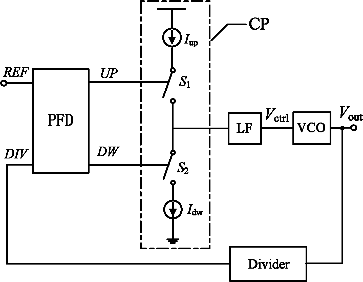
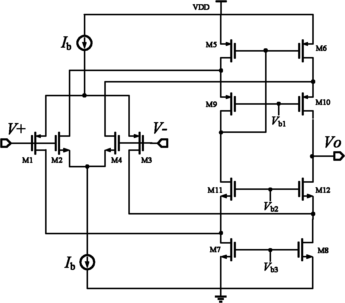
[0020] see figure 2 , The charge pump circuit in the charge pump phase-locked loop of the present invention includes a self-bias current mirror 1, a charge and discharge circuit 2, a replica circuit 3, a pre-charge bias circuit 4 and a rail-to-rail operational amplifier circuit A. in:

[0021] Self-bias current mirror circuit 1 is provided with resistor R, MOS transistors M1, M2, M3 and reference current source I ref , one end of the resistor R is connected to the gate of the MOS transistor M1 and the reference current source I ref , the reference current source I ref The other end is connected to the power supply VDD, the other end of the resistor R is connected to the drain of the MOS transistor M1 and the gate of M2, the source of the MOS transistor M1 is connected to the drain of M2, the source of the MOS transistor M2 is connected to the drain of M3, and the MOS transistor M3 The gate of M3 is connected to the power supply VDD, and the source of M3 is grounded.

[00...


PUM


Abstract

The invention relates to a charge pump circuit in a charge pump phase-locking loop, which is provided with an automatic bias current mirror circuit, a charging and discharging circuit, a copy circuit, a precharging bias circuit and a rail-to-rail operational amplification circuit. The automatic bias current mirror circuit is provided with a resistor R, three MOS (Metal Oxide Semiconductor) pipes and a reference current source. The charging and discharging circuit is provided with a charging and discharging current source consisting of a charging and discharging switch pipe and four MOS (MetalOxide Semiconductor) pipes. The copy circuit is copied from a charging and discharging circuit structure, and corresponding transistor sizes are correspondingly equal. The precharging bias circuit isprovided with five MOS pipes, the input end of the rail-to-rail operational amplification circuit is bridged between the charging and discharging circuit and the copy circuit, and the output end is connected with a charge pump charging current source.

Description

technical field [0001] The present invention relates to a charge pump phase-locked loop (CPPLL), in particular to a charge pump circuit in a charge pump phase-locked loop, which uses a MOS process to achieve high-precision current matching under a wide output voltage, and has a high pre-charging current, which can It is directly applicable to the application of charge pump phase-locked loop circuit in radio frequency and analog integrated circuits. Background technique [0002] The phase-locked loop (PLL) frequency synthesizer circuit uses the principle of feedback to control the output variable, so as to realize the automatic tracking of the frequency of the output signal to the frequency of the input signal. Charge pump phase-locked loop (CPPLL) is the mainstream of current phase-locked loop circuit design. Because of its advantages of wide capture range, short capture time, large linear range, high speed and low power consumption, it is widely used in modern communication...

Claims


Application Information

Patent Timeline
IPC IPC(8): H02M3/07H03L7/08
Inventor 李智群郑爽爽王志功
Owner SOUTHEAST UNIV
Why Eureka
Try Eureka