
Mobile terminal and charging circuit thereof

A charging circuit, mobile terminal technology, applied in battery circuit devices, circuit devices, current collectors, etc., can solve problems such as large heat generation, and achieve the effect of increasing charging current and reducing temperature

Inactive Publication Date: 2016-09-28
HUIZHOU TCL MOBILE COMM CO LTD
View PDF4 Cites 3 Cited by
  • Summary
  • Abstract
  • Description
  • Claims
  • Application Information

AI Technical Summary

Problems solved by technology

[0004] In the existing technology, the heat source when charging the mobile phone mainly comes from the conversion loss of the charging circuit. At present, the efficiency of most charging chips is 80% to 90%, so that 10% to 20% of the energy is converted into heat and dissipated to the surface of the mobile phone. , the greater the charging current, the greater the loss, and the greater the heat

Method used


Image

  • Mobile terminal and charging circuit thereof
  • Mobile terminal and charging circuit thereof

Examples


Embodiment Construction

[0018] Hereinafter, embodiments of the present invention will be described in detail with reference to the accompanying drawings. This invention may, however, be embodied in many different forms and should not be construed as limited to the specific embodiments set forth herein. Rather, the embodiments are provided to explain the principles of the invention and its practical application, thereby enabling others skilled in the art to understand the invention for various embodiments and with various modifications as are suited to particular intended uses.

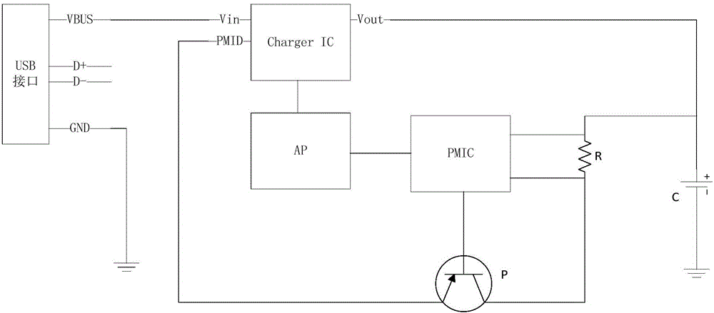
[0019] see figure 1 , figure 1 It is a circuit block diagram of the charging circuit of the mobile terminal of the present invention. The charging circuit of the mobile terminal includes a USB interface, a switch charging module Charger IC connected to the USB interface, a processing control module AP connected to the switch charging module Charger IC, a power management module PMIC connected to the processing control modul...


PUM


Abstract

The invention discloses a charging circuit of a mobile terminal. The charging circuit comprises a USB interface, a switch charging module which is connected with the USB interface, a processing control module which is connected with the switch charging module, a power supply management module which is connected with the processing control module, a triode which is connected with the switch charging module and the power supply management module, a resistor which is connected with the power supply management module and the triode, and a battery which is connected with the switch charging module and the resistor. According to the charging circuit of the mobile terminal, the switch charging module and a linear charging circuit formed by integration of the power supply management module are simultaneously configured to start charging so as to realize two-path parallel charging. Charging current is enhanced, and the generated heat is dispersed to two charging circuits so as to achieve the effect of temperature reduction.

Description

technical field [0001] The invention relates to the field of mobile terminals, in particular to a mobile terminal and a charging circuit thereof. Background technique [0002] Mobile terminals have been widely used in people's life and work. For example, mobile terminals such as mobile phones carried by people are used more and more frequently in life and work, so the capacity of mobile phone batteries is required to be larger and larger. [0003] With the increasing battery capacity of mobile phones, the long charging time has become a pain point for users. In order to speed up the charging time of the mobile phone, it is necessary to increase the charging current, but when charging with a high current, it will cause a lot of heat in the mobile phone, making parts of the mobile phone hot and reducing the user experience. [0004] In the existing technology, the heat source when charging the mobile phone mainly comes from the conversion loss of the charging circuit. At pres...

Claims


Application Information

Patent Timeline
Patent Type & Authority Applications(China)
IPC IPC(8): H02J7/04
CPCH02J7/00H02J7/045
Inventor 顾瞻
Owner HUIZHOU TCL MOBILE COMM CO LTD
Learn More