
Heat pipe cyclic power machine

A heat pipe cycle and power machine technology, applied in the field of power machines, can solve the problems of poor power generation efficiency of power generation coils, poor heat conduction and power generation effects, and low device efficiency.

Inactive Publication Date: 2011-08-10
舒明
View PDF4 Cites 7 Cited by
  • Summary
  • Abstract
  • Description
  • Claims
  • Application Information

AI Technical Summary

Problems solved by technology

[0003] At present, although there are power devices that use the characteristics of heat pipes to transmit and convert heat energy, these devices have low efficiency, large energy loss, and limited functions.
For example: a "heat pipe generator" disclosed in a Chinese patent, a technology for generating electricity using steam inside a heat pipe disclosed in U.S. Patent No. 4186559, etc. These structures using heat pipe power generation devices have the problem of poor heat conduction and power generation effects
Although some can maintain a good heat conduction structure inside the heat pipe to maintain a vacuum, and form the inner and outer magnet rotors and power generation coils to cooperate to generate power, there are still certain deficiencies in them, such as: the absorption of the "heat pipe generator" The heat rate and heat dissipation rate are not very good; there is a certain energy loss in the steam transmission process; the energy conversion rate between the steam and the fan blade (or magnet rotor) is low; the power generation efficiency of the power generation coil is not good and the function has limitations, etc.

Method used


Image

  • Heat pipe cyclic power machine
  • Heat pipe cyclic power machine
  • Heat pipe cyclic power machine

Examples


Embodiment Construction

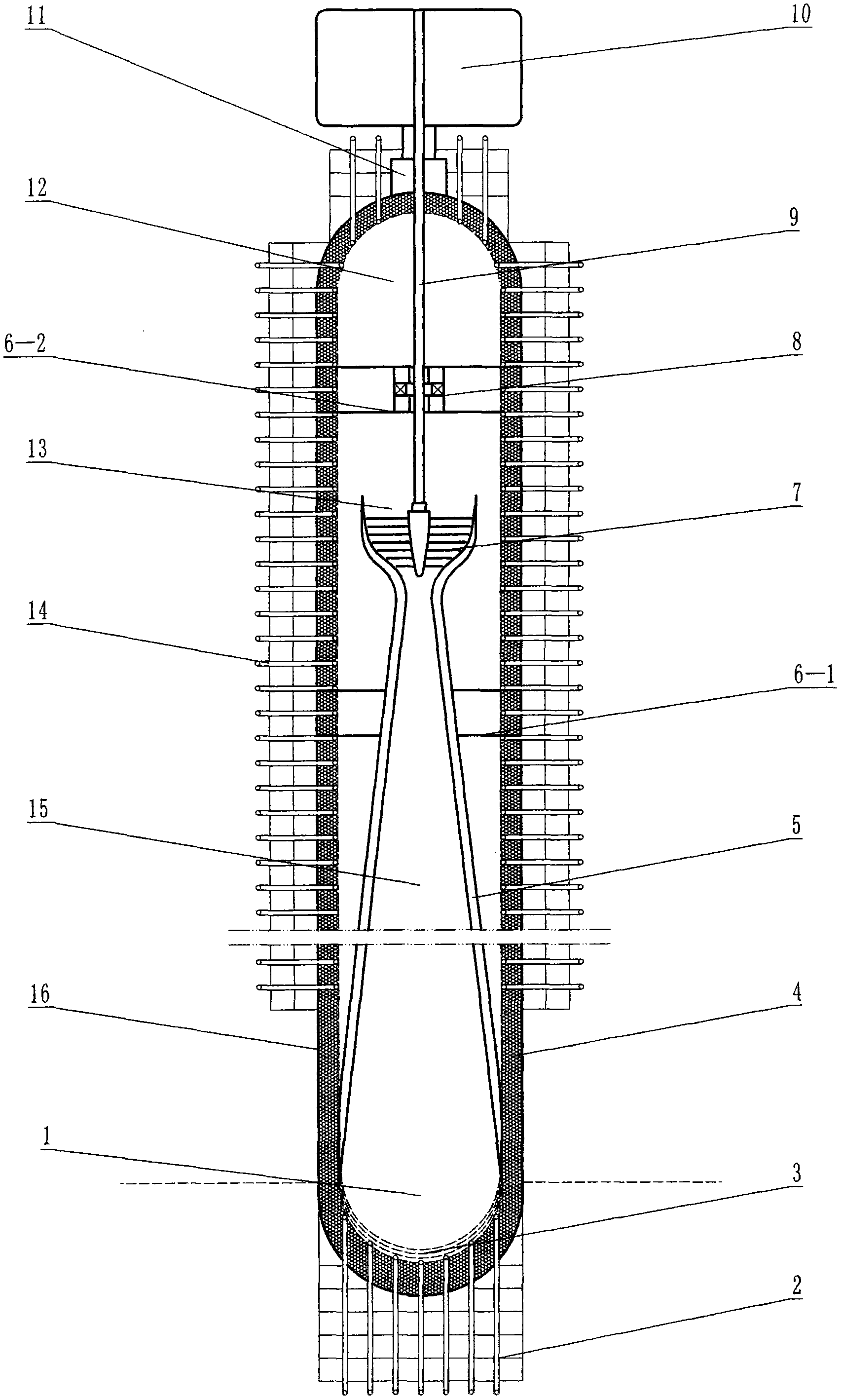
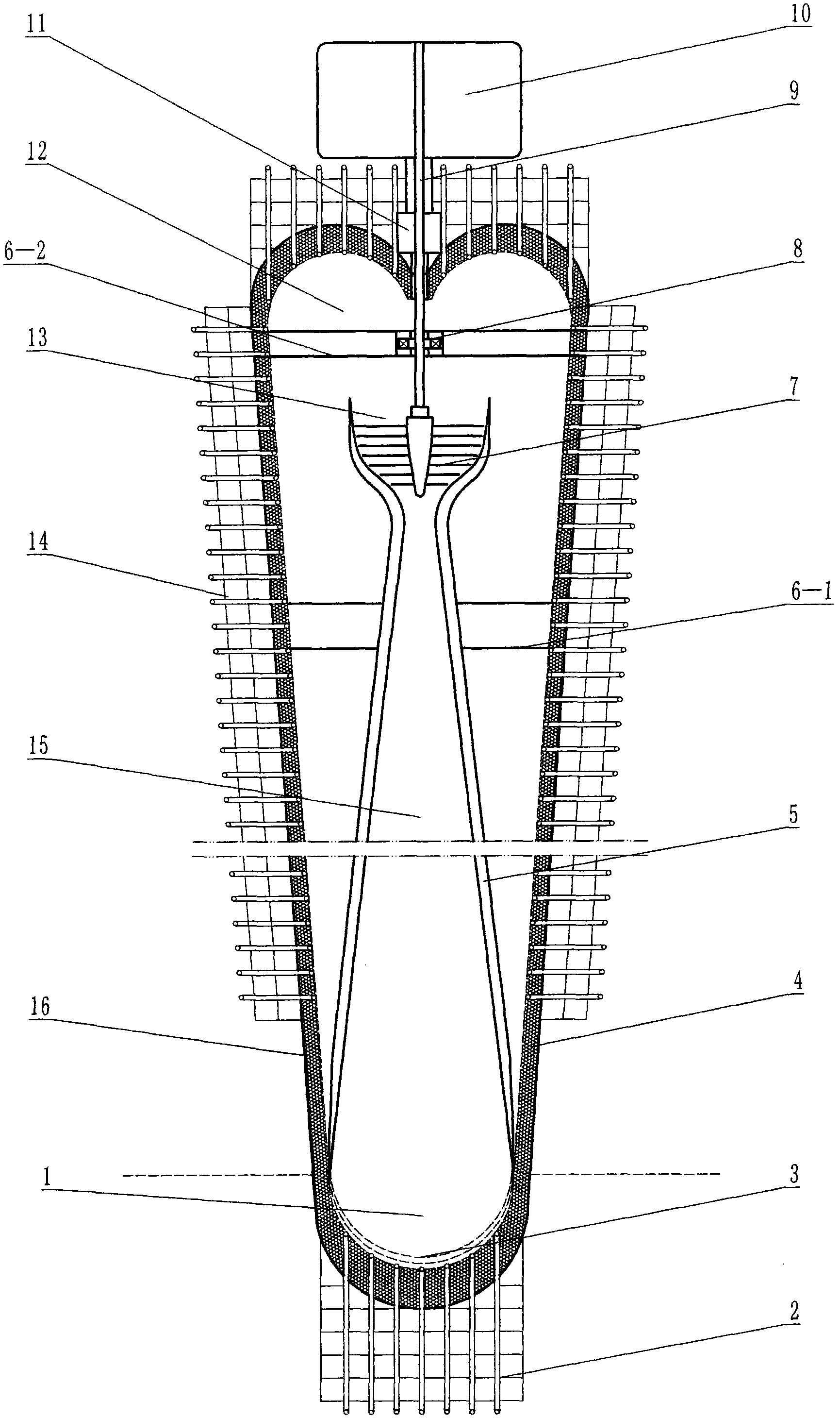
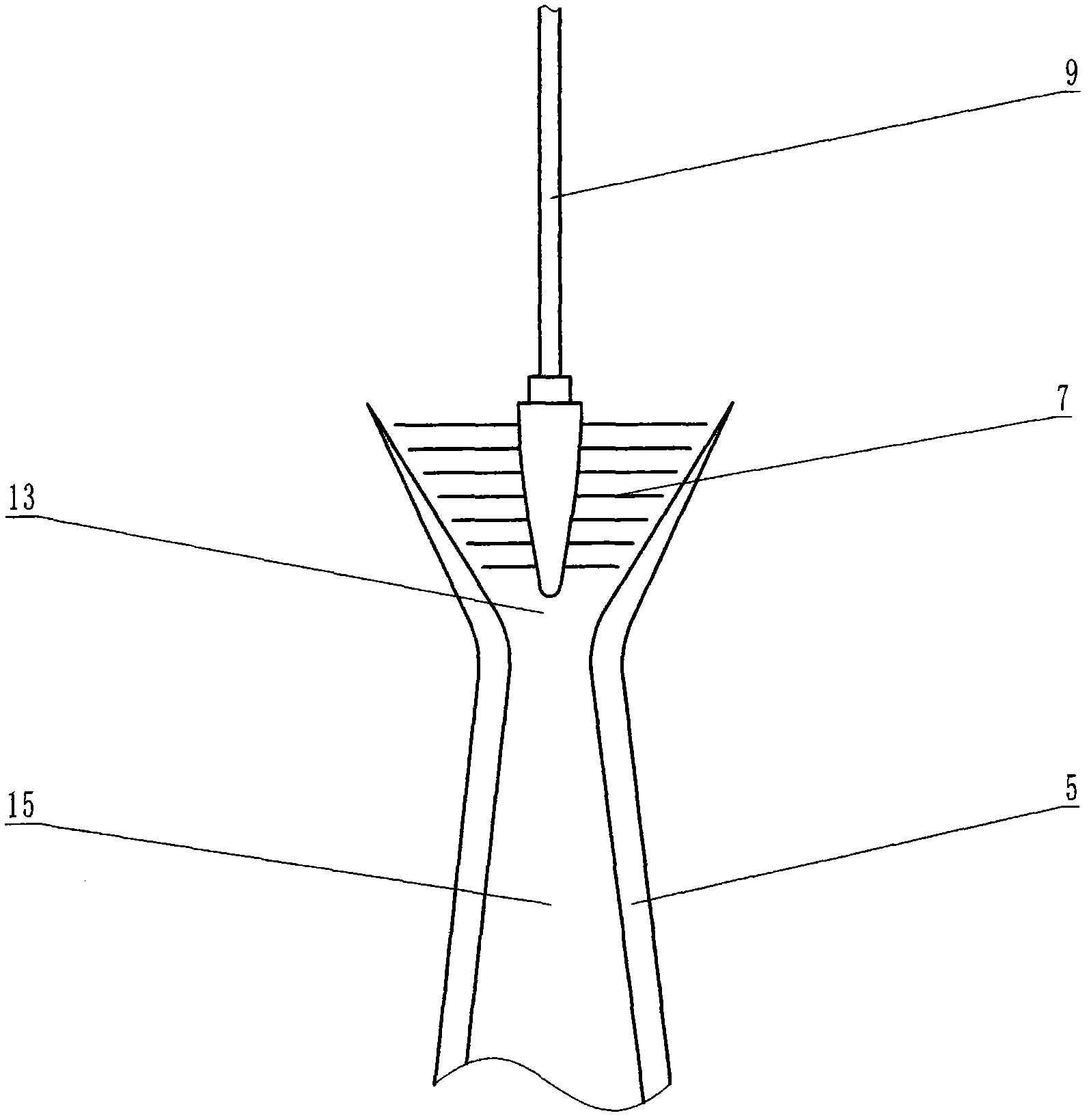
[0021] As shown in the accompanying drawings: the heat pipe cycle power machine is composed of a heat pipe and a turbine power generation system. The body of the heat pipe is composed of the pipe wall 16, the liquid-absorbing core 4 and the working medium 3; The inner surface of the tube wall 16 of the heat pipe is provided with a liquid-absorbing wick 4 with a larger volume, surface area and permeability, and a smaller capillary effective radius. The axial vertical section of the liquid-absorbing core 4 on the inner surface of the pipe wall 16 on the upper part of the condensation chamber 12 is larger than the axial vertical section of the liquid-absorbing core 4 in other parts, and can be set as a meniscus-shaped liquid-absorbing section. core. The inner cavity of the lower part of the heat pipe is the evaporation chamber 1, which is filled with the working fluid 3, and the inner cavity from the evaporation chamber 1 to the nozzle 13 is a tapered lumen 15 with a gradually d...


PUM


Abstract

The invention discloses a heat pipe cyclic power machine consisting of a heat pipe and a turbine power generation system. The main body of the heat pipe consists of a pipe wall, a liquid absorption core and a working medium; the cavity body of the heat pipe consists of an evaporation cavity, a condensation cavity, a tapered pipe cavity, a vacuum heat insulation cavity and a nozzle; the liquid absorption core is arranged on the inner surface of the pipe wall of the heat pipe; the inner cavity of the lower part of the heat pipe is the evaporation cavity; the working medium is filled in the evaporation cavity; the inner cavity from the evaporation cavity to the nozzle is the tapered pipe cavity of which the cross sectional area is reduced gradually; the nozzle is formed on the upper part of the tapered pipe cavity; the vacuum heat insulation cavity is formed outside the tapered pipe cavity and the nozzle; the inner cavity of the upper part of the nozzle and the inner cavity outside the vacuum heat insulation cavity are condensation cavities; and the turbine power generation system consists of a multi-level blade, a supporting mechanism, a bearing, a rotating shaft, a magnetofluid sealing device and a power output system. The heat pipe cyclic power machine makes an actual contribution to aspects such as new energy power generation, energy saving and emission reduction, mechanical transmission and the like, and pushes the sustainable development of cyclic economy and the significant development of low-carbon economy and green economy.

Description

technical field [0001] The invention relates to a power machine, which is a cycle power machine which utilizes the characteristics of heat pipes for heat transmission and transformation. Background technique [0002] The heat pipe is a heat transfer element invented by G.M.Grover of the Los Alamos National Laboratory in the United States in 1963. It makes full use of the heat conduction principle and the rapid heat transfer properties of the refrigeration medium, and relies on the phase change of its internal working fluid to achieve heat transfer. thermal element. Its thermal conductivity exceeds that of any known metal. Compared with silver, copper, aluminum and other metals, a heat pipe per unit weight can transfer several orders of magnitude more heat, and its heat transfer ability is thousands or even tens of thousands of times higher. Known as thermal superconductivity. The heat pipe is widely used in aerospace, military, Coal mining, chemical industry, electric pow...

Claims


Application Information

Patent Timeline
Patent Type & Authority Applications(China)
IPC IPC(8): F01K27/00
Inventor 舒明舒海胡芳
Owner 舒明
Learn More