
Anode carbon block with centre joint groove

An anode carbon block and slot groove technology is applied in the field of prebaked anode carbon block structure and preparation for aluminum electrolytic cells, and can solve the problem of easy cracking, affecting the quality of aluminum liquid and electrolyte, and large damage to the carbon block force system structure. question

Inactive Publication Date: 2011-08-10
高德金
View PDF0 Cites 5 Cited by
  • Summary
  • Abstract
  • Description
  • Claims
  • Application Information

AI Technical Summary

Problems solved by technology

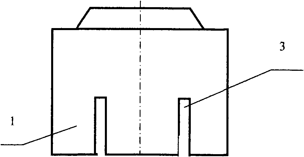
The purpose of opening these two narrow grooves is to make the anode carbon block discharge CO gas during the production process of the electrolyzer and improve the conductivity efficiency, but there are also two shortcomings in the anode carbon block with two narrow grooves. First, the two narrow grooves are filled with adsorbed and bonded carbon coke particles during the roasting process. Because the gap is too narrow, it is difficult to clean, or the cleaning is not clean. After the carbon coke particles are brought into the electrolytic cell, it will affect the relationship between the aluminum liquid and the electrolyte. The second is: Compared with the anode carbon block with grooves in the whole part, after two narrow grooves are opened on the section of the anode carbon block, and the bottom section is divided into four small unit sections, the overall end face force system of the carbon block The structure is greatly damaged, and it is easy to break during the roasting process, resulting in a decrease in the yield of carbon blocks

Method used


Image

  • Anode carbon block with centre joint groove
  • Anode carbon block with centre joint groove
  • Anode carbon block with centre joint groove

Examples


Embodiment Construction

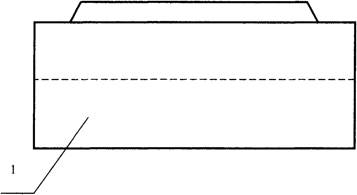
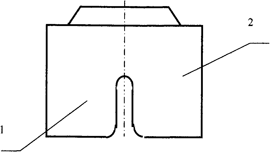
[0015] The present invention is an anode carbon block with a central slit groove. Its manufacturing process is basically the same as that of the current general solid anode carbon block and the anode carbon block with two debt grooves. The difference is It is: at the bottom of the original solid anode carbon block (1), open a middle slot groove (2) with a width of more than 20mm, a width of about 35mm, and a height of about 250mm along the length direction of the carbon block (1). figure 1 , figure 2 shown. , to overcome the current common slotted carbon block to open two narrow grooves (3) with a width less than 18mm, in order to overcome the difficulty of cleaning the coke particles in the narrow groove, and to open two grooves to cause the carbon block to be easily damaged, and the yield is low shortcoming,

[0016] After the anode carbon block with the middle slot groove is applied to the production of the aluminum electrolytic cell, the middle slot groove (2) is condu...


PUM


Abstract

The invention relates to an anode carbon block with a centre joint groove. In the invention, the centre joint groove with the width more than 20mm is formed upwards at the bottom of the anode carbon block along the length centre line of the anode carbon block so as to replace two narrow grooves of the existing general carbon block. The anode carbon block with the centre joint groove has the advantages that in the process of roasting, the gas exhausting passage can be shortened, a smoke volatile substance generated in the carbon block is easy to exhaust, and the porosity is reduced, so that the interior of the carbon block is roasted and heated evenly, the stress is balance, the carbon block has less possibility of cracking, and the yield and quality of the anode carbon product are improved; and after the carbon block is roasted, the roasted coke particles in the groove of the carbon block are easy to clean, the pollution of the roasted coke particles to the electrolyte and liquid aluminium in the process of electrolyzation is reduced, and the heat-conducting property of the carbon block is improved, thereby being beneficial for CO gas in the aluminium electrolysis to separate out and achieve the purpose of saving the current drain of the aluminium electrolysis.

Description

Technical field: [0001] The invention is a novel prebaked anode carbon block structure and preparation method for an aluminum electrolytic cell. Background technique: [0002] There are basically two structural forms of anode carbon blocks for aluminum electrolytic cells that are commonly used today. One is a rectangular solid anode carbon block; the disadvantages of this anode carbon block are manifested in two aspects. The volatile substances of the flue gas generated inside are discharged from the inside to the outside. Due to the large volume of the carbon block, the exhaust channels (microscopic pores) are longer and more, which easily leads to a higher porosity of the finished carbon block. Among them, the inside and outside of the carbon block are heated to uneven temperature, the diffusion and shrinkage of thermal stress are also inconsistent, and it is also easy to produce defects such as uneven density of carbon block, many cracks, and easy breakage; the second is ...

Claims


Application Information

Patent Timeline
IPC IPC(8): C25C3/12
Inventor 高德金高伟
Owner 高德金
Learn More