
Magnetic field sensor and magnetic field tester

A magnetic field sensor and magnetic liquid technology, which is applied in the use of magneto-optical equipment to measure the magnetic field, the size/direction of the magnetic field, etc., can solve the problems of low precision, high price, and inconspicuous straight lines, etc., and achieve good stability , Small size, simple system effect

Inactive Publication Date: 2011-08-03
陆樟献
View PDF1 Cites 18 Cited by
  • Summary
  • Abstract
  • Description
  • Claims
  • Application Information

AI Technical Summary

Problems solved by technology

[0004] In the prior art, S.Y.Yang et al. published "Origin and applications of magnetically tunable refractive index of magnetic fluid films" in "Applied Physics Letters" 2004, Vol. The characteristics of the change of the refractive index difference of the liquid film with the magnitude of the magnetic field are used for optical sensing research, but because the straight line is not obvious, the transmission loss is only 1.13%, so there is a lack of high precision.
[0005] In October 2008, Di Ziyun and others from Shanghai Jiaotong University applied for an invention patent application for "A device for detecting magnetic field changes based on changes in the refractive index of magnetic fluids". The publication number is CN 101281237A. The sensitivity of the device disclosed in this document has reached 0.0025nm / Gs, its working range can be from 0Gs to 1500Gs, but due to the need to use a spectrum analyzer to detect, the price is higher

Method used


Image

  • Magnetic field sensor and magnetic field tester
  • Magnetic field sensor and magnetic field tester
  • Magnetic field sensor and magnetic field tester

Examples


Embodiment Construction

[0018] Embodiments of the present invention will be described in detail below in conjunction with the accompanying drawings. This embodiment is carried out on the premise of the technical solution of the present invention, and the detailed implementation and specific operation process are given, but the protection scope of the present invention is not limited to the following embodiments.

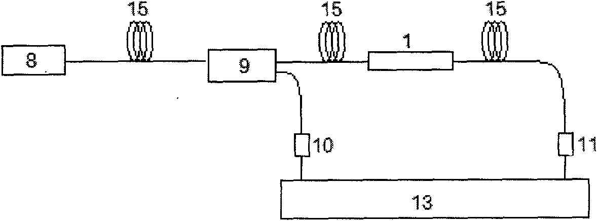
[0019] attached figure 1 And attached figure 2 Respectively, the present invention is based on the magnetic liquid-based double-thin-clad long-period fiber grating-intensity transmissive magnetic field sensor and the magnetic liquid-based double-thin-clad long-period fiber grating-intensity reflective magnetic field sensor; image 3 And attached Figure 4 They are structural schematic diagrams of the magnetic field tester for transmission type and reflection type magnetic field sensors of the present invention respectively.

[0020] Such as figure 1 As shown, this embodiment is a trans...


PUM


Abstract

The invention discloses a double thin-cladded long-period fiber grating intensity type magnetic field sensor based on magnetic liquid. The intensity type magnetic field sensor is characterized by consisting of double thin-cladded long-period fiber gratings and magnetic liquid. The invention further discloses a magnetic field tester for the double thin-cladded long-period fiber grating intensity type magnetic field sensor employing the magnetic liquid, comprising an LED light source, a 3dB optical coupler, a double thin-cladded long-period fiber grating intensity type magnetic field sensor employing the magnetic liquid, a photoelectric detector, and a data receiving and signal processing device. The double thin-cladded long-period fiber grating intensity type magnetic field sensor has the technical characteristics of small volume, simple system, excellent stability, safety, reliability, easiness in grid connection, and special advantage that the performance of the sensor can be designed according to actual requirements. Through the adoption of the magnetic field tester, the changes of a magnetic field can be detected on the basis of the changes in the light intensity of the senor under the effect of the magnetic field at a temperature between 0 DEG C and 80 DEG C, and the sensitivity is extremely high, while the measurement resolution of the magnetic field reaches 0.1 oersted in the range from 0 oersted to 1000 oersted.

Description

technical field [0001] The invention relates to an optical fiber sensing technology, in particular to a double-thin cladding long-period optical fiber grating intensity magnetic field sensor based on magnetic liquid and a magnetic field tester based on the sensor. Background technique [0002] Magnetic liquid is a stable colloidal system formed by nano-scale strong magnetic particles dispersed in the base liquid. It has both the magnetism of solid matter and the fluidity of liquid. It is a new type of functional material. Under the action of an external magnetic field, the magnetic liquid has a strong magneto-optical effect and is a new type of optical material. [0003] Long-period fiber grating is a very good transmission-type band-stop filter, which has the advantages of small additional loss, no back reflection, no electromagnetic interference, and full compatibility with optical fibers, making it widely used in optical fiber communications. The period of the long-perio...

Claims


Application Information

Patent Timeline
IPC IPC(8): G01R33/032
Inventor 陆樟献
Owner 陆樟献
Learn More