
Solid fuel gasification and combustion device and boiler

A solid fuel and combustion equipment technology, applied in the direction of solid heating fuel, combustion method, lighting and heating equipment, etc., can solve the problems of easy generation of soot and dust, atmospheric environment pollution by soot and dust, insufficient combustion, etc.

Inactive Publication Date: 2011-08-03
QUZHOU YUNRUI IND DESIGN
View PDF6 Cites 4 Cited by
  • Summary
  • Abstract
  • Description
  • Claims
  • Application Information

AI Technical Summary

Problems solved by technology

However, for a long time, the combustion process of combustion equipment has been dominated by direct combustion. Insufficient combustion, low thermal efficiency, serious waste of coal resources, and easy to produce soot and dust pollute the environment.
Soot is generated by the dehydrogenation, polymerization or condensation of hydrocarbon fuels. Once the soot is formed, it is very difficult to burn it. Therefore, combustion equipment that uses solid fuel to directly burn will cause soot and dust to pollute the atmosphere. environmental phenomenon

Method used


Image

  • Solid fuel gasification and combustion device and boiler
  • Solid fuel gasification and combustion device and boiler
  • Solid fuel gasification and combustion device and boiler

Examples


Embodiment 1

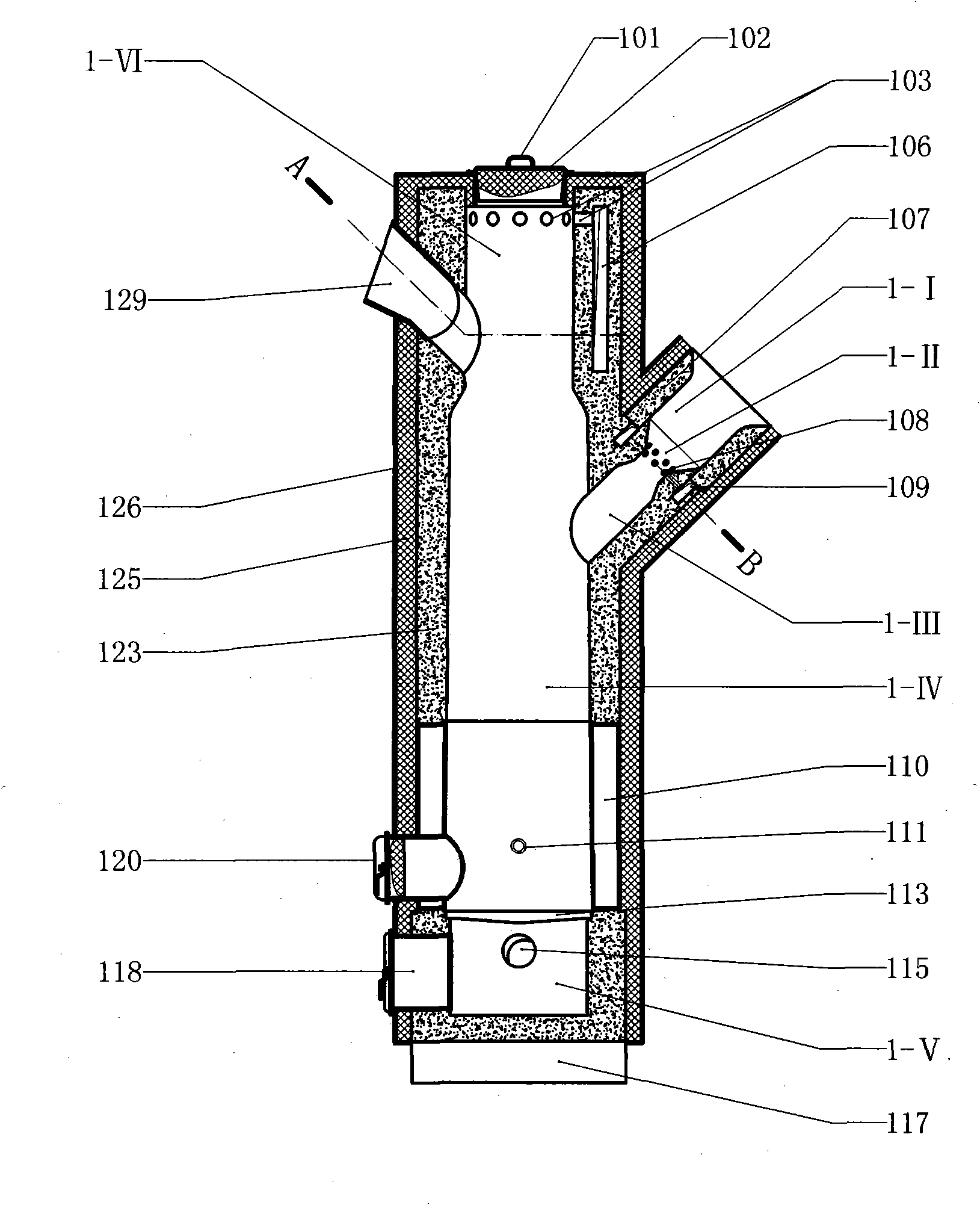
[0028] Example 1 figure 1Shown is a gasification combustion equipment using solid fuel, wherein the gasification furnace (1-IV) is formed by the inner space of the vertical rotary furnace wall, and the rotary furnace wall includes a refractory layer a (123) and water Cover (110), refractory layer a (123) is on the water jacket (110), and the outer layer of refractory layer a (123) and water jacket (110) is insulation layer a (125), and insulation layer a (125) The outer layer is shell a (126); there is an air passage (1-VI) above the gasification furnace (1-IV), and the furnace wall of the air passage (1-VI) is the wall of the gasification furnace (1-IV). In the extension section, air holes a (103) are set on the furnace wall of the air passage (1-VI). The air chamber a (106), the air hole a (103) is connected to the annular air chamber a (106), and the annular air chamber a (106) has an air outlet port a (130) to connect; between the air passage (1-VI) and There is a feed / a...

Embodiment 2

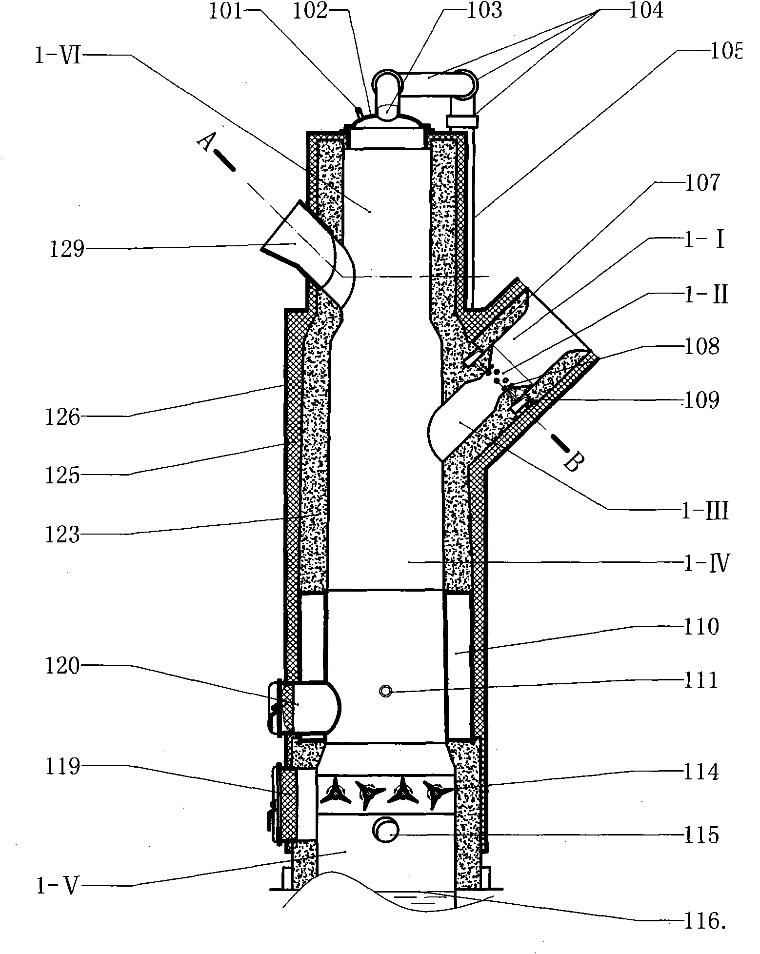
[0029] Example 2 figure 2 In the shown embodiment, the grate (113) in the first embodiment is replaced by a slag breaker (114), and the slag breaker (114) is made up of a rotating shaft and a crushing knife, wherein the crushing knife is in the form of a trident, and the fork It is a pyramid structure, and there are multiple crushing knives on each rotating shaft, and the rotating shaft is manually shaken or mechanically rotated by a motor-reduction mode; the air hole a (103) changes the stove top cover (102) in the air passage (1-VI). ), the air hole a (103) is connected to the air pipe (105) through the universal joint assembly (104), and the air pipe (105) is connected to the blower air inlet of the air supply system. The bottom of the air chamber (1-V) in this embodiment is a water seal (116), and the slag removal is a mechanical slag removal method. out.

Embodiment 3

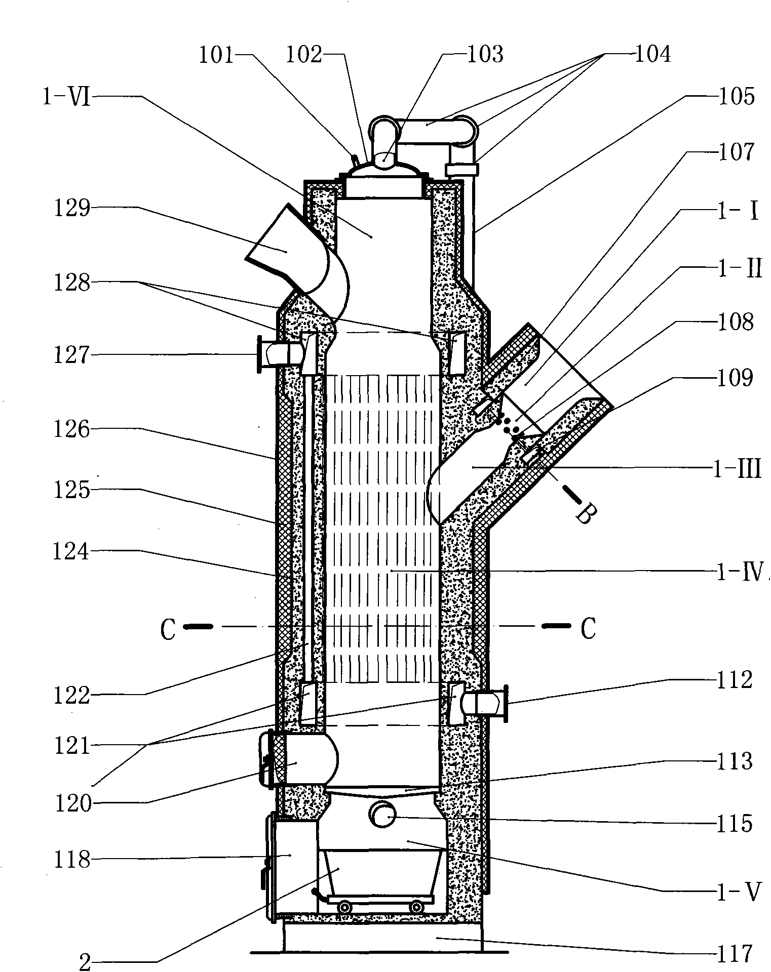
[0030] Example 3 image 3 In the shown embodiment, the refractory furnace wall (124) is used to replace the refractory layer a (123) and the water jacket (110) in the first embodiment or the second embodiment, and the refractory furnace wall (124) is a cylindrical structure, In the body of wall of the refractory furnace wall (124), there are annular air chamber b (128), pipe cavity (122) and annular air chamber c (121), annular air chamber b (128) is on the top, annular air chamber c (121 ) in the lower part, the pipe cavity (122) is connected between the annular air chamber b (128) and the annular air chamber c (121), and the pipe chamber (122) is distributed in a multi-pipe manner on the wall of the refractory furnace wall (124) In the body, the annular air chamber b (128) is connected to the air inlet port (127), and the annular air chamber c (121) is connected to the air outlet port b (112). When this embodiment is in operation, the combustion-supporting air enters the an...


PUM


Abstract

The invention relates to a solid fuel gasification and combustion device and a boiler, and relates to the combustion device. The combustion device and the boiler are characterized in that a gasification furnace is composed of the inner space of a vertical type revolved body furnace wall; an air duct is arranged above the gasification furnace; a charging opening and an air inlet are arranged on a side wall between the air duct and the gasification furnace; an ignition door is arranged at the lower part of the gasification furnace; an air chamber is arranged below the gasification furnace; the outlet of gasification objects is arranged from the middle section of the gasification furnace; a secondary combustion device comprises an air entraining channel, an annular air chamber d, an air hole b, a fire opening and a combustion stabilizing chamber, wherein the air inlet end of the air entraining channel is connected to the outlet of the gasification objects of the gasification furnace; the air outlet end of the air entraining channel is connected to the fire opening; the fire opening is connected to the combustion stabilizing chamber; the combustion stabilizing chamber is composed of the inner space of a combustion stabilizing ring; the furnace wall body at the fire opening section is provided with the annular air chamber d; the annular air chamber d is connected by a blast hole; and the annular air chamber d is communicated with the fire opening through the air hole b. In the invention, the solid fuel is subjected to gasification combustion, the combustion efficiency of the solid fuel is improved, clean combustion is realized, and the pollution to environment is reduced.

Description

technical field [0001] The present invention relates to combustion equipment, in particular to combustion equipment and boilers using solid fuel. Background technique [0002] The solid fuels available to human beings include coal, biomass such as agricultural and forestry wastes, and municipal solid waste. my country is a major producer of coal and domestic waste. At the same time, my country is rich in biomass resources, with a large amount of agricultural waste, Firewood forests and wood processing wastes are available for use, and agricultural wastes such as straw and chaff are more than 700 million tons per year, equivalent to more than 300 million tons of standard coal. [0003] In my country's energy structure, coal is the primary energy source and is mainly used as boiler fuel. In recent years, with the increasingly serious situation of environmental protection and the depletion of fossil fuels, under the support of national policies, biomass energy is actively used,...

Claims


Application Information

Patent Timeline
IPC IPC(8): F24B1/183F24B1/189F24B1/191C10J3/00F22B1/00F24H1/44F23L15/00
CPCY02E20/34
Inventor 周开根
Owner QUZHOU YUNRUI IND DESIGN
Learn More