
Forge welding method for manufacturing wind power main shaft

A wind power spindle and forging welding technology, which is applied in the direction of manufacturing tools and other manufacturing equipment/tools, can solve the problems that cannot meet the design requirements of large wind power spindles, the performance of the forging body is quite different, and the structure density of the spindle is low. The effect of improving material utilization, improving operation stability and safety, and improving comprehensive mechanical properties

Active Publication Date: 2011-07-06
JIANGSU JINYUAN FORGE +1
View PDF0 Cites 13 Cited by
  • Summary
  • Abstract
  • Description
  • Claims
  • Application Information

AI Technical Summary

Problems solved by technology

However, as the power of wind power generation increases, the weight of the wind power main shaft also increases rapidly. If the overall forging method is still used to manufacture the wind power main shaft, the tonnage requirements of the forging equipment are getting higher and higher, so that it cannot be implemented; especially if the large wind power main shaft is used. The overall casting method is not suitable for working under alternating load conditions due to the low structure density of the spindle and poor physical and chemical properties of the material.
If tungsten argon arc welding, metal argon arc welding, plasma welding, laser welding and other methods are used to weld split large-wall thickness forgings, it is necessary to open a large groove and fill a large amount of metal, and the performance of the filler metal is much lower than that of The performance of forgings is easy to cause a large difference between the performance of the weld area and the forging body, and a large amount of heat input during the welding process produces large residual stress and welding deformation. Design requirements
So far, there is no manufacturing method for wind power spindles that can replace integral forging or achieve the effect of integral forging

Method used


Image

  • Forge welding method for manufacturing wind power main shaft
  • Forge welding method for manufacturing wind power main shaft
  • Forge welding method for manufacturing wind power main shaft

Examples


Embodiment 1

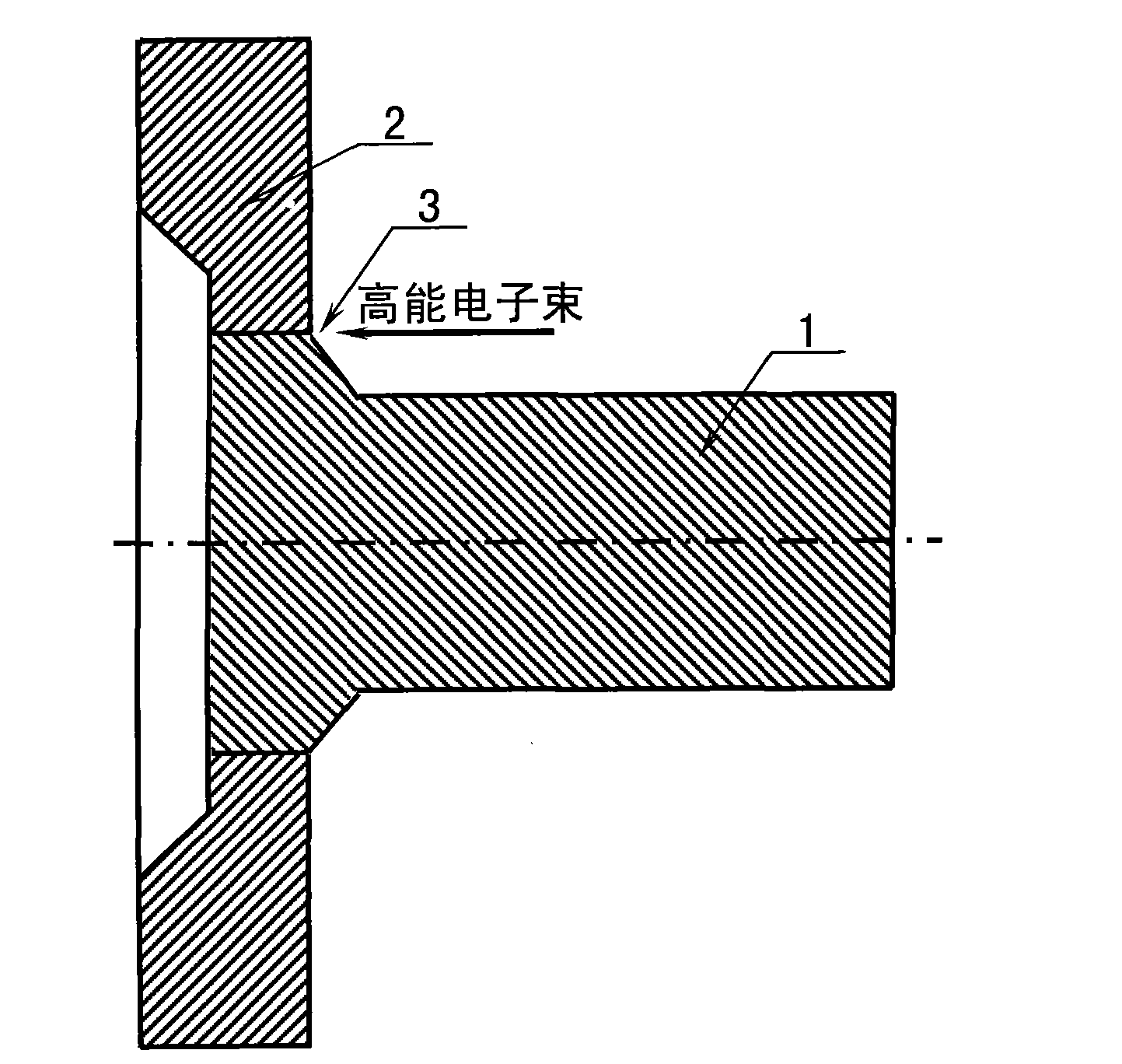
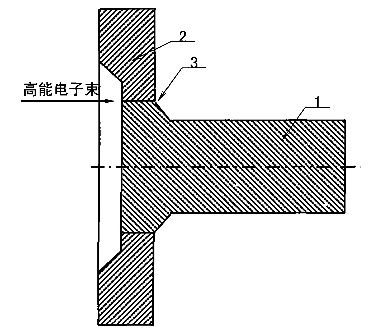
[0022] Example 1. combine figure 1 , figure 2 , image 3 and Figure 4 Taking the manufacture of a 1.5ΩW wind power main shaft as an example by implementing high-energy electron beam welding on the shaft side or the flange side along the axial direction from the wind power main shaft in the present invention to manufacture a 1.5ΩW wind power main shaft as an example, the specific steps are as follows:

[0023] Step 1, forging and welding structure design. According to the requirement that the weight of each split structural part of the wind power spindle forging is less than the tonnage of the forging equipment, forging equipment that meets the design requirements of forging and welding structures and medium-pressure or high-voltage high-energy electron beam deep penetration welding with a weld penetration depth of δ100mm is adopted machine, determine that the wind power spindle forging and welding split structural parts are Φ1600mm hollow flange (2) and Φ750mm connecting...

Embodiment 2

[0030] Example 2. combine figure 1 and Figure 5 , taking the manufacture of a 1.0ΩW wind power main shaft by high-energy electron beam welding from a direction perpendicular to the axis of the wind power main shaft as an example, the specific steps are as follows:

[0031] Step 1, forging and welding structure design. According to the requirement that the weight of each split structural part of the wind power main shaft forging and welding is less than or equal to the tonnage of the forging equipment, forging equipment that meets the design requirements of the forging and welding structure and a medium-pressure or high-voltage high-energy electron beam deep melting with a weld penetration depth of δ193mm are adopted. For the welding machine, it is determined that the wind power spindle forging and welding split structural parts are Φ1200mm solid flange (5) and Φ380mm end shaft (4). The depth of penetration guarantees the penetration of the end shaft portion of Φ380 mm to for...

Embodiment 3

[0038] Example 3. combine figure 1 and Figure 6 , taking the wind power main shaft of the split structure of the three components proposed by the present invention and implementing high-energy electron beam deep penetration welding twice to manufacture a 2.5ΩW wind power main shaft as an example, the specific steps are as follows:

[0039] Step 1, forging and welding structure design. According to the requirement that the weight of each split structural part of the wind power main shaft forging is less than the tonnage of the forging equipment, the forging equipment that meets the design requirements of the forging and welding structure and the weld penetration depth of δ180mm and 250mm medium-voltage or high-voltage high-energy electron beam depth are adopted. For the fusion welding machine, determine the forged and welded split structural parts of the wind power main shaft as the Φ1800mm hollow flange (2), the mandrel (6) and the end shaft (4) with a diameter less than or...


PUM


Abstract

The invention relates to a forge welding method for manufacturing a wind power main shaft, wherein the wind power main shaft is manufactured by using the following processes in turn: forge welding structure design, parts forge and press, mechanical processing, deep penetration welding, quality detection, heat treatment and finished product detection, wherein the process of forge welding structure design is for confirming the split structure of the wind power main shaft; the process of parts forge and press is for forging the split structured parts; the process of mechanical processing is for milling a to-be-welded surface; the process of deep penetration welding is for performing the deep penetration welding by using high-energy electronic beams; the process of quality detection is for detecting the melted depth and quality of welding gaps; the process of heat treatment is for eliminating the stress after welding; and the process of finished product detection is for detecting the whole property of a blank. By using the wind power main shaft which is manufactured by using the forge welding method, the phenomenon of increasing the demand on the tonnage of forged and pressed equipment caused by the increasing of the weight of the wind power main shaft can be avoided. By utilizing the heat treatment for eliminating the stress after welding, the wind power main shaft can bear the repeated loading impact under poor working conditions, is suitable for bearing the violent-typhoon huge impact load in the coastal or offshore area, and is beneficial to increasing the running stability and safety of a wind turbine.

Description

technical field [0001] The invention relates to a manufacturing method of a main shaft of a wind power generator, in particular to a forging welding manufacturing method of a main shaft of a wind power generator. Background technique [0002] The wind turbine main shaft is a key part of the wind power machine. The existing wind power main shaft generally adopts the integral forging manufacturing method, which is beneficial to ensure the physical and chemical properties and organizational structure uniformity of the wind power main shaft material, and is suitable for harsh working environments. Operates under heavy alternating loads. When the generating power of the wind turbine is small, the weight of the wind power main shaft is also small, and the overall forging method for manufacturing the wind power main shaft does not require high forging equipment tonnage. However, as the power of wind power generation increases, the weight of the wind power main shaft also increases...

Claims


Application Information

Patent Timeline
IPC IPC(8): B23P23/04
Inventor 葛艳明周琦王克鸿彭勇鲁磊
Owner JIANGSU JINYUAN FORGE
Learn More