
Zero resonance unit-loaded broadband planar inverted-F antenna

A resonant unit and broadband technology, applied in the field of wireless communication equipment design, can solve the problems of unsuitable microwave circuit integration, complex processing, large volume, etc., and achieve the effect of simple structure, easy processing, and wide bandwidth

Inactive Publication Date: 2011-06-22
SOUTH CHINA UNIV OF TECH
View PDF2 Cites 19 Cited by
  • Summary
  • Abstract
  • Description
  • Claims
  • Application Information

AI Technical Summary

Problems solved by technology

However, most of these antennas are double-layer folded structures, which are large in size and complex in processing, and are not suitable for integration with microwave circuits. Therefore, it is necessary to find new design ideas to design a broadband antenna with small size, simple processing, and easy integration with microwave circuits. antenna

Method used


Image

  • Zero resonance unit-loaded broadband planar inverted-F antenna
  • Zero resonance unit-loaded broadband planar inverted-F antenna
  • Zero resonance unit-loaded broadband planar inverted-F antenna

Examples


Embodiment 1

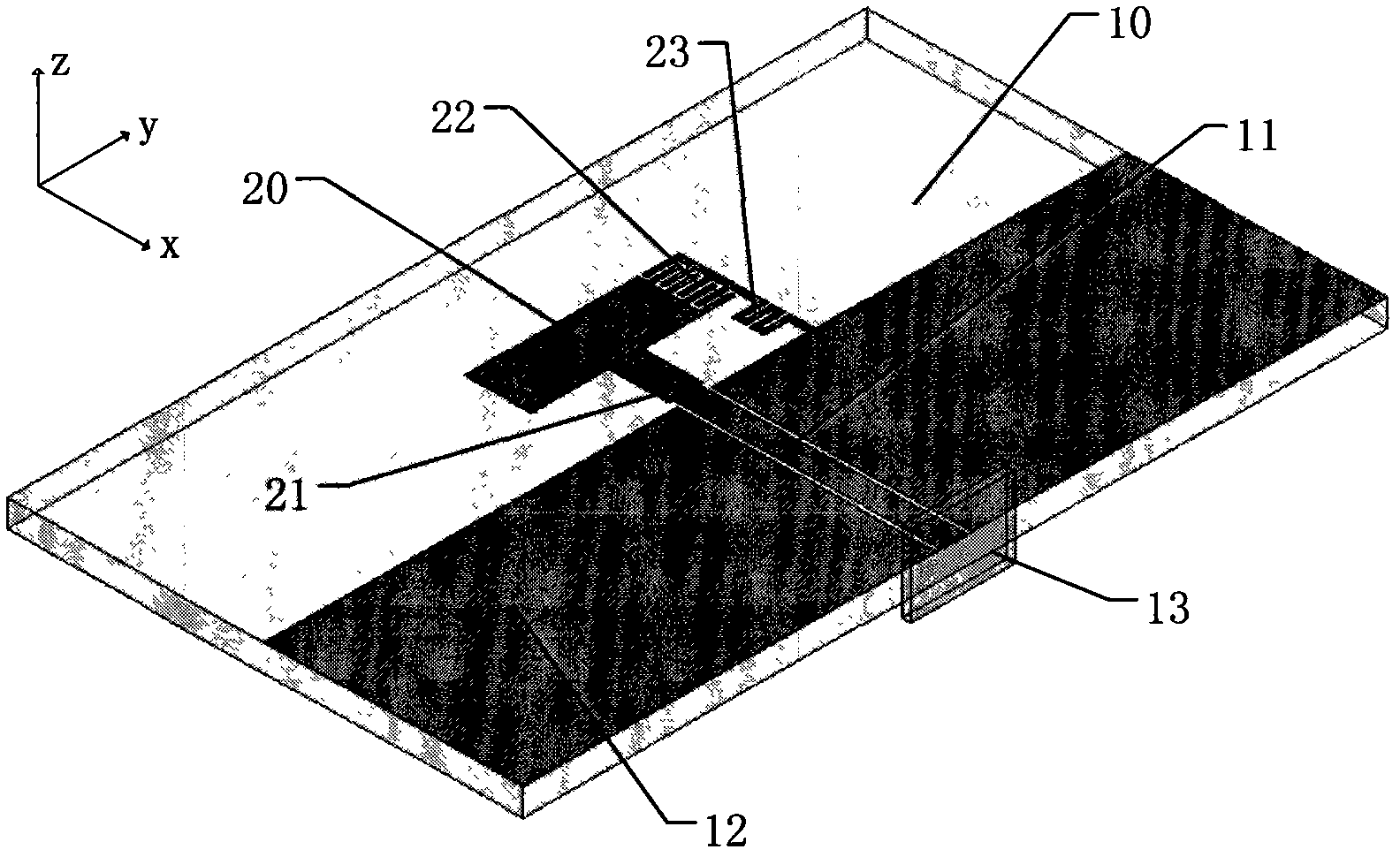
[0030] Such as figure 1 As shown, a broadband planar inverted-F antenna loaded with a zero-resonance unit includes an upper layer microstrip structure, a bottom dielectric substrate 10, and an input and output port 13; the upper layer microstrip structure includes a coplanar waveguide transmission line 11, an antenna body 20, a feeder Incoming line 21, loading interdigitated capacitor 22, and grounding thin-line inductance 23, one end of the coplanar waveguide transmission line 11 is connected to the input and output port 13, and the other end is directly fed into the antenna main body 20 through the feeding line 21, and the antenna main body 20- The terminal is provided with a loaded interdigitated capacitor 22 and a grounded thin-wire inductor 23, and the grounded thin-wire inductor 23 is connected to the floor 12; the loaded interdigitated capacitor 22 and the grounded thin-wire inductor 23 form a zero resonance unit together with the antenna main body 20; The upper microst...

Embodiment 2

[0044]The structure of this embodiment is the same as that of Embodiment 1 except for the following features: the relative dielectric constant of the underlying dielectric substrate is 1, and the thickness is 0.1 mm.

Embodiment 3

[0046] The structure of this embodiment is the same as that of Embodiment 1 except for the following features: the relative dielectric constant of the underlying dielectric substrate is 100, and the thickness is 5 mm.


PUM

PropertyMeasurementUnit
Thicknessaaaaaaaaaa
Thicknessaaaaaaaaaa
Thicknessaaaaaaaaaa

Abstract

The invention discloses a zero resonance unit-loaded broadband planar inverted-F antenna. The antenna comprises a top microstrip structure, a bottom dielectric substrate and an input / output port, wherein the top microstrip structure comprises a coplanar waveguide transmission line, an antenna main body, a feed line, a loading interdigital capacitor and a ground thin-wire inductor, wherein one end of the coplanar waveguide transmission line is connected with the input / output port and the other end is fed to the antenna main body through the feed line; one terminal of the antenna main body is provided with the loading interdigital capacitor and the ground thin-wire inductor; the ground thin-wire inductor is connected with a floor board; the loading interdigital capacitor, the ground thin-wire inductor and the antenna main body together form a zero resonance unit; and the top microstrip structure is arranged on the bottom dielectric substrate. By loading the zero resonance unit in a broadband planar inverted-F antenna, the problems of large area, complex machining and the like of the broadband planar inverted-F antenna are solved; therefore, the zero resonance unit-loaded broadband planar inverted-F antenna has the advantages that the size is small, the broadband is broad, the structure is simple, the broadband planar inverted-F antenna is easy to machine and the like.

Description

technical field [0001] The invention belongs to the field of wireless communication equipment design, in particular to a broadband planar inverted-F antenna loaded with a zero-resonance unit. Background technique [0002] With the rapid development of mobile communication, antennas are used as transceiver devices of wireless communication equipment, and people put forward higher and higher requirements for their performance. Because of its compact structure, low profile, light weight, easy manufacture, and easy microwave circuit integration and many other advantages, planar inverted-F antennas are widely used in wireless communication devices and become the main form of built-in antennas. In addition to the traditional GSM and DCS, Bluetooth and WLAN have already been added to many terminal devices in the current wireless services. Therefore, it is an urgent need for antenna design to cover multiple frequency bands on a planar inverted-F antenna. [0003] At present, most b...

Claims


Application Information

Patent Timeline
IPC IPC(8): H01Q9/30H01Q13/08
Inventor 褚庆昕于洪泽
Owner SOUTH CHINA UNIV OF TECH
Learn More