
Method, device and system for detecting pulse noise

A technology for detecting pulse and pulse noise, applied in the field of communication, can solve the problems of complex implementation of the mean square error method, low detection sensitivity, missed detection and false alarm, etc., to achieve high accuracy and sensitivity, complex detection methods, and implementation methods. simple effect

Active Publication Date: 2011-06-15
HUAWEI TECH CO LTD
View PDF3 Cites 5 Cited by
  • Summary
  • Abstract
  • Description
  • Claims
  • Application Information

AI Technical Summary

Problems solved by technology

[0006] In the process of realizing the present invention, the inventors found that the detection accuracy of the power detection method is low, and there are problems of missed detection and false positives, and when the power of the pulse noise is small, it is difficult to detect the pulse noise by this method. The detection sensitivity is low; the implementation of the mean square error method is relatively complicated

Method used


Image

  • Method, device and system for detecting pulse noise
  • Method, device and system for detecting pulse noise
  • Method, device and system for detecting pulse noise

Examples


Embodiment 1

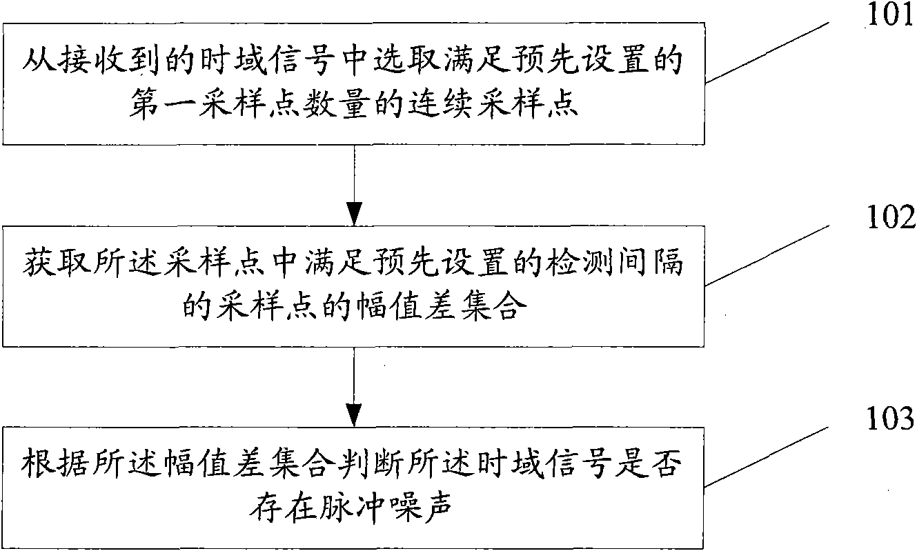
[0036] Such as figure 1 As shown, the method for detecting impulse noise provided by the embodiment of the present invention includes:

[0037] Step 201, selecting consecutive sampling points satisfying the preset number of first sampling points from the received time-domain signal;

[0038] In this embodiment, the time-domain signal may be a time-domain sampling point output by a digital-to-analog converter or a decoder inside a digital demodulator, or may be a time-domain sampling point output by other modules. Before selecting sampling points, first set a sampling number, which is called the first sampling point number. For example, the first sampling point number can be set as one symbol sampling point, or two symbol sampling points, or other fixed values, etc. According to the set fixed number of sampling points, the sampling points conforming to the first number of sampling points are continuously selected from the time domain sampling points.

[0039] Step 202, obtain...

Embodiment 2

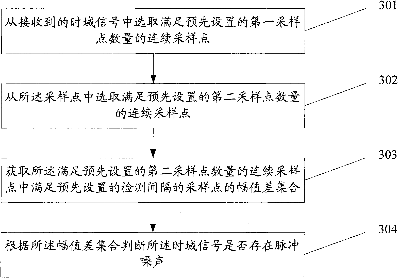
[0047] Such as image 3 As shown, another embodiment of the present invention provides a method for detecting impulse noise, including:

[0048] Step 301, select consecutive sampling points satisfying the preset number of first sampling points from the received time-domain signal; the specific implementation method of this step is the same as the implementation method of step 201 in Embodiment 1, and will not be repeated here.

[0049] Step 302, selecting consecutive sampling points satisfying the preset number of second sampling points from the sampling points;

[0050] In this embodiment, if the sampling points of one or more symbols are selected in step 301, the number of sampling points is large, and the calculation in subsequent steps is more complicated. In order to simplify the processing method, only a part of the sampling points satisfying the first number of sampling points can be calculated and processed, the amplitude difference information of this part of the sam...


PUM


Abstract

The embodiment of the invention discloses a method, device and system for detecting pulse noise, relating to the field of communication, and aiming to solve the problems that the pulse noise detection method is complex and has lower detection accuracy and sensitivity in the prior art. The technical scheme provided by the invention comprises the following steps: selecting continuous sampling points in accordance with the number of preset first sampling points from received time domain signals; acquiring an amplitude difference set of sampling points in accordance with preset detection intervals in the sampling points; and judging whether the time domain signals have pulse noise according to the amplitude difference set. The technical scheme provided by the embodiment of the invention can be applied to a pulse noise detection technique of various digital signal processing systems such as DSL (digital subscriber line), Cable and other wired access modes, wireless access, WIFI (wireless fidelity) or 3G (the 3rd generation telecommunication) and the like.

Description

technical field [0001] The present invention relates to the communication field, in particular to a method, device and system for detecting impulse noise. Background technique [0002] In a communication system, impulse noise is generated due to electromagnetic interference, failure of the communication system, and changes in the state of electrical switches. Impulse noise is discontinuous and consists of irregular pulses or noise spikes with short duration and large amplitude. In digital communication, if the impulse noise is too large, it will completely change the phase and amplitude information of the signal carrier, resulting in bit errors. Therefore, how to detect and eliminate impulse noise is of great significance to practical systems. [0003] Currently, existing technologies can provide two methods for detecting impulse noise: [0004] One is the power detection method, which calculates the power of sampling points in the time domain or carrier power in the freq...

Claims


Application Information

Patent Timeline
IPC IPC(8): H04B17/00H04B1/10H04B17/309
Inventor 潘稻潘众李莹贾玉臣阿米尔・法兹罗拉西
Owner HUAWEI TECH CO LTD
Learn More