
Acoustic resonator and sound chamber

A technology of acoustic resonators and acoustic chambers, which is applied in the direction of sound-emitting devices, instruments, and sound absorption, and can solve problems such as difficulty in installing resonators and enlargement

Inactive Publication Date: 2011-06-08
YAMAHA CORP
View PDF7 Cites 12 Cited by
  • Summary
  • Abstract
  • Description
  • Claims
  • Application Information

AI Technical Summary

Problems solved by technology

In addition, the resonator needs to increase its volume as the resonance frequency decreases, so the width dimension of the resonator will be larger than the height dimension of the resonator
This makes it difficult to mount the resonator as it will interfere with surrounding components

Method used


Image

  • Acoustic resonator and sound chamber
  • Acoustic resonator and sound chamber
  • Acoustic resonator and sound chamber

Examples


Embodiment Construction

[0043] The invention will now be described in more detail by way of example with reference to the accompanying drawings, wherein like parts shown in the various drawings are indicated by like reference numerals.

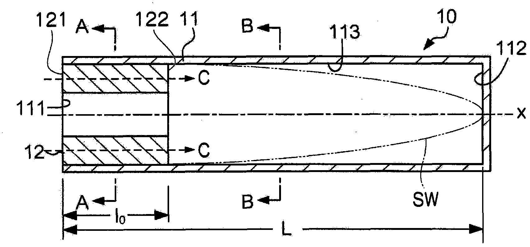
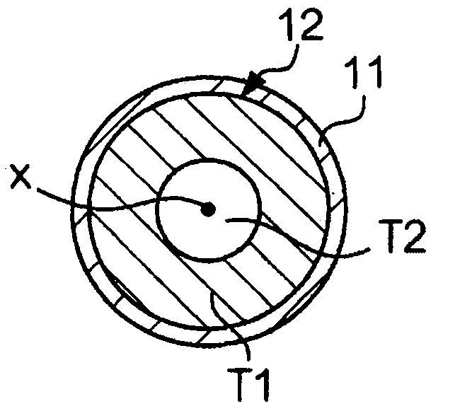
[0044] figure 1 is a perspective view of the acoustic resonator 10 according to the first embodiment of the present invention. The acoustic resonator 10 has the shape of a cylindrical tube with an open end (on the left) and an opposite closed end (on the right). The acoustic resonator 10 is divided into a pipe member 11 and a resistance member 12 . The pipe member 11 (serving as a housing of the acoustic resonator 10) is formed in a cylindrical shape and is made of metal or plastic. The pipe member 11 having one open end extends in the length direction. The resistance member 12 is a cylindrical assembly defined within opposing circular surfaces and having a cylindrical cavity therein lengthwise through the middle portion. The resistance member 12 is engaged insid...


PUM


Abstract

The present invention provides an acoustic resonator and a sound chamber. The acoustic resonator adaptable to a sound chamber is designed to decrease a sound pressure while increasing a particle velocity of medium particles in a low frequency range without increasing the overall size thereof. The acoustic resonator is constituted of a pipe member having one opening end and a resistance member embracing a high resistance region and a low resistance region. The resistance member is inserted into the pipe member such that one end thereof matches the opening end of the pipe member whilst the other end thereof is disposed at a predetermined position inside a hollow cavity of the pipe member. The high resistance region embraces an antinode region of the particle velocity distribution with respect to a standing wave occurred in the hollow cavity at a resonance frequency, thus causing an acoustic phenomenon decreasing the resonance frequency compared to a single unit of the pipe member.

Description

technical field [0001] The present invention relates to acoustic resonators and acoustic chambers. [0002] This application claims priority from Japanese Patent Application No. 2009-272891 and Japanese Patent Application No. 2010-239875, the contents of which are incorporated herein by reference. Background technique [0003] Conventionally, various sound absorbing structures using acoustic resonators have been developed and disclosed in various documents such as Patent Documents 1, 2 . [0004] Patent Document 1: Japanese Patent Application Publication No. H07-302087 [0005] Patent Document 2: Japanese Patent Application Publication No. H08-121142 [0006] Patent Document 1 discloses a sound absorbing structure aimed at reducing sound pressure in a low frequency range, in which open ends of a plurality of resonance tubes having different lengths, each having an open end and an opposite closed end, adjoin each other. Patent Document 2 discloses an intake noise reduction...

Claims


Application Information

Patent Timeline
Patent Type & Authority Applications(China)
IPC IPC(8): G10K11/16G10K11/172E04B1/99
CPCF01N1/02G10K11/02F01N2490/15F01N1/023F01N2310/10F01N1/04F01N2490/155G10K11/04
Inventor 棚濑廉人深津圭一
Owner YAMAHA CORP
Learn More