
Molded transformer provided with fire extinguishing device

A fire-extinguishing device and transformer technology, applied in transformer/inductor parts, transformer/inductor coils/windings/connections, electrical components, etc., can solve problems such as coil burnout, inoperability, component loss, etc., to achieve shortened piping, Rapid fire extinguishing effect and durability improvement effect

Active Publication Date: 2016-12-21
HYOSUNG HEAVY IND CORP
View PDF6 Cites 2 Cited by
  • Summary
  • Abstract
  • Description
  • Claims
  • Application Information

AI Technical Summary

Problems solved by technology

However, the problems in the prior art documents are that since the gas cannot be injected directly to the surroundings of the coil where the fire occurs, the coil that actually caught fire will be burned due to the fire, and even the surrounding parts will be destroyed by the fire.
[0005] Moreover, once the transformer is installed, it will be used for a long time, usually more than ten years, and in the prior art literature, the structure used for fire extinguishing is not located in the inner space where the transformer is installed, but outside, so the structure for fire extinguishing is easy. Aging due to the influence of the external environment, when it is actually needed, it cannot operate

Method used


Image

  • Molded transformer provided with fire extinguishing device
  • Molded transformer provided with fire extinguishing device
  • Molded transformer provided with fire extinguishing device

Examples


Embodiment Construction

[0031] A part of embodiments of the present invention will be described in detail below with exemplary drawings. It should be noted that when assigning reference signs to constituent elements in each drawing, even if the same constituent elements are attached to different drawings, they should be given the same reference numerals as much as possible. In addition, when describing the embodiments of the present invention, if it is considered that the specific description of related known structures or functions hinders the understanding of the embodiments of the present invention, the detailed description thereof will be omitted.

[0032] In addition, terms such as first, second, A, B, a, b, etc. may be used when describing constituent elements of the embodiments of the present invention. Such terms are only used to distinguish the constituent element from another constituent element, and the nature or order or sequence of the constituent elements will not be limited by the term...


PUM


Abstract

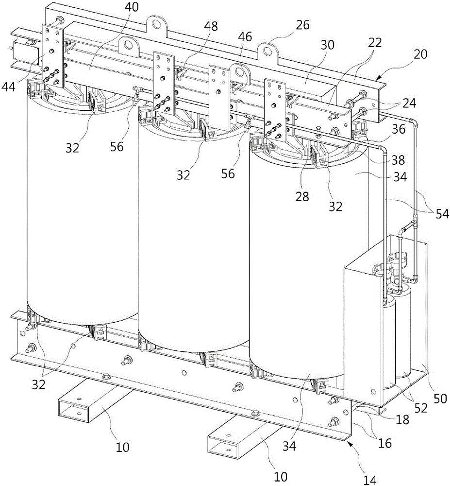
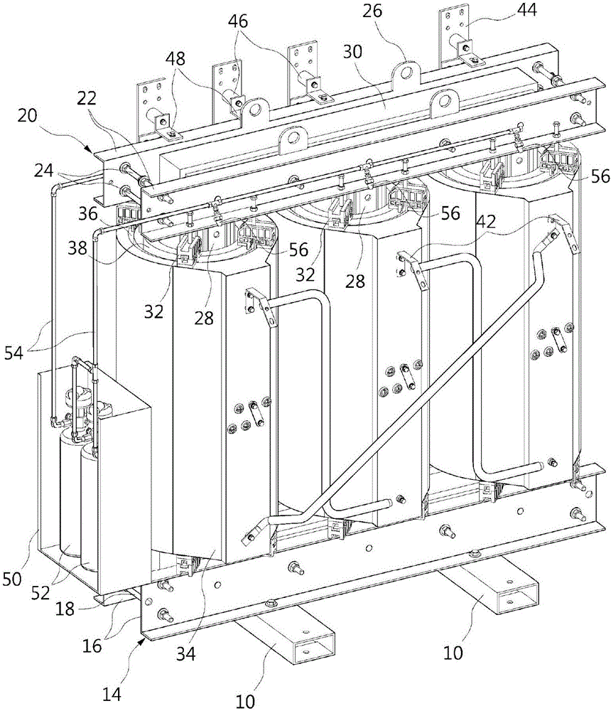
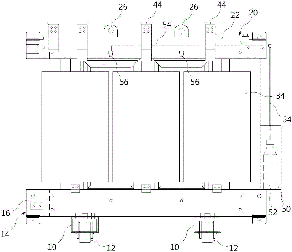
The present invention relates to a molded transformer provided with a fire extinguishing device. According to the present invention, a lower frame (14) is positioned on a base (10), and an upper frame (20) is supported by the lower frame (14) and provided at the upper part of the lower frame (14). The lower frame (14) and the upper frame (20) are connected by a tie rod (28), and a steel core (30) is supported by the lower frame (14), the upper frame (20) and the tie rod (28). Secondary coils (38) are provided to surround the steel core (30), and primary coils (34) are provided to allow the secondary coils (38) to penetrate the inside thereof. A case (50) is provided at one end part of the lower frame (14), and fluid containers (52) are provided in an area partitioned by the case (50). A section of a pipe (54) connected with the fluid containers (52) extends along the upper frame (20). A nozzle (56) is provided at the pipe (54) for spraying fluid between the primary coil (34) and the secondary coil (38) or between the outer surfaces of the primary coils (34). According to the present invention, since a fire-extinguishing fluid is directly sprayed at the primary coils (34) and the secondary coils (38) at which a fire can occur, a fire-extinguishing operation can be performed more rapidly.

Description

technical field [0001] The present invention relates to a molded transformer, and more specifically, to a molded transformer equipped with a fire extinguishing device capable of quickly extinguishing a fire when the molded transformer itself is on fire. Background technique [0002] Molded transformers are encased in epoxy to insulate the transformer's primary and secondary coils from surrounding components. Generally, a coil is placed in a mold in a wound state, epoxy resin is injected into the mold, and the coil is wrapped with the epoxy resin to form a molded transformer. Although such a molded transformer has a primary coil and a secondary coil covered with epoxy resin, there is a risk of fire due to sparks or the like generated during operation. [0003] That is, since the transformer carries a high voltage, it is difficult to extinguish the fire when a fire occurs during the operation of the transformer. Especially because of the high voltage, workers trying to extin...

Claims


Application Information

Patent Timeline
Patent Type & Authority Applications(China)
IPC IPC(8): H01F27/00H01F27/32
CPCH01F27/00H01F27/32
Inventor 金泳柱朴范俊文炳哲金宰仲
Owner HYOSUNG HEAVY IND CORP
Learn More