
Cost effective paintball gun system

a paintball gun and cost-effective technology, applied in the field of pneumatic marking guns, can solve the problems of cylinder affecting paintball velocity, gun to go off target, blowback and open pneumatic circuit, etc., and achieve the effect of eliminating other deficiencies, reducing the firing mechanism, and providing efficiency

Inactive Publication Date: 2011-02-08
KORE OUTDOOR US INC
View PDF13 Cites 23 Cited by
  • Summary
  • Abstract
  • Description
  • Claims
  • Application Information

AI Technical Summary

Benefits of technology

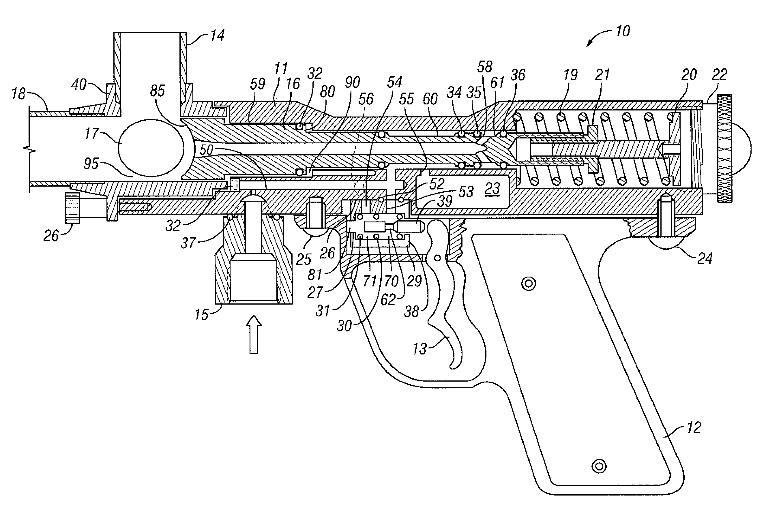
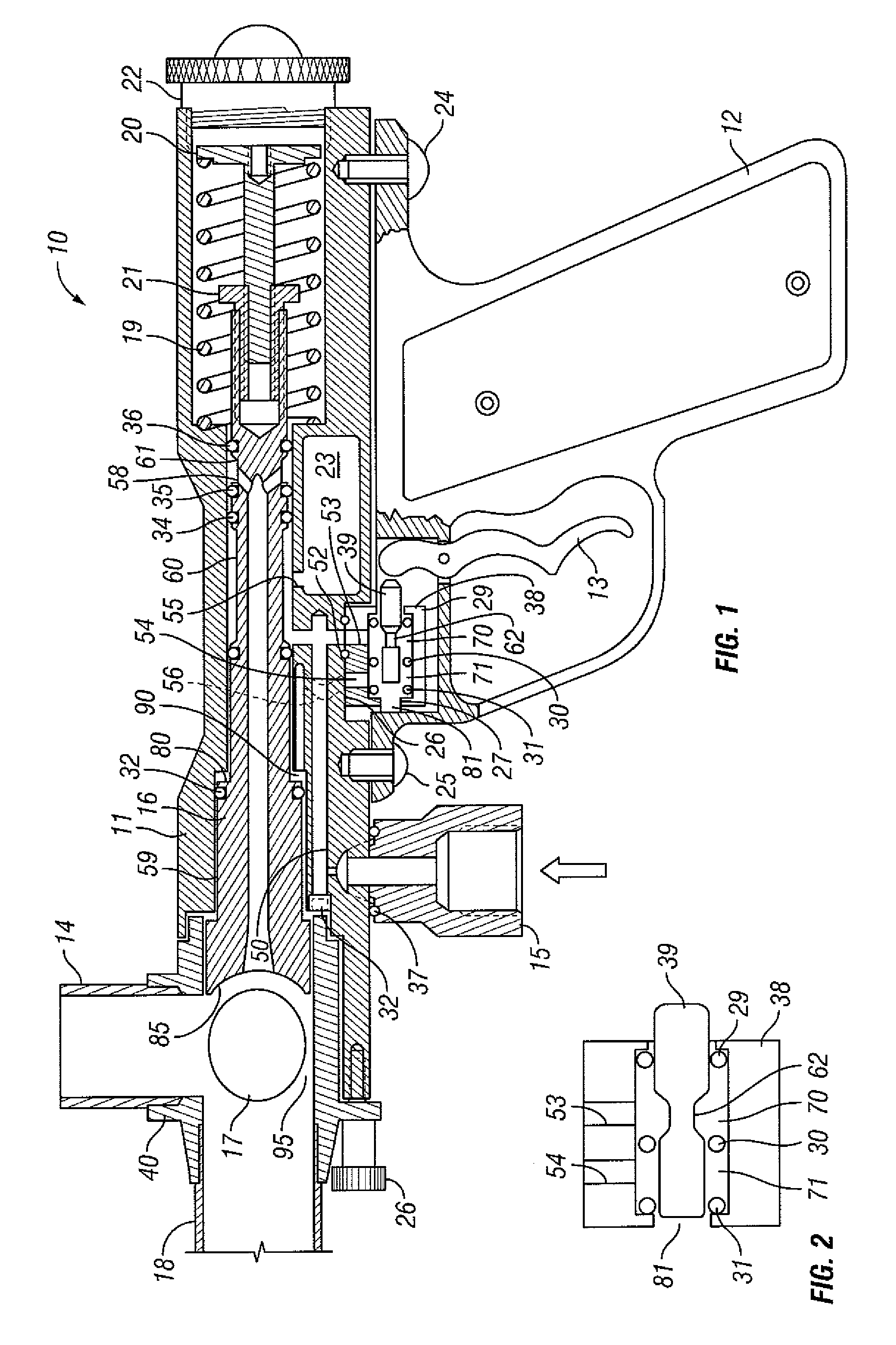
[0015]A paintball gun according to the present invention overcomes the problems of the prior compressed gas paintball guns by providing a fully pneumatic gun design with simplified firing mechanism and eliminating other deficiencies related to the prior art paintball guns. Firing mechanism is being activated by simple two way flow valve with short stroke which enables the player to do rapid firing. A gas storage chamber provides efficiency to the paintball gun by storing exact amount of compressed gas to fire a paintball, and it is located in the lower portion of the gun body. The main components of the firing mechanism include gun body, hollow bolt, a gas storage chamber and several passageways configured to communicate with each other. The trigger and the two way valve activates the firing mechanism. When bolt is in retracted position gas from gas source enters and fills gas storage chamber and also enters the two way valve. When the trigger is pulled, the gas from the two way valve is directed to the piston located on the bolt and causes the bolt to move forward. While the bolt is moving forward, first access from compress gas source to gas storage chamber is closed and than when paintball is loaded into the barrel gas storage chamber is being opened to fire the paintball. When trigger is released, a gas in front of the bolt piston is being vented to the atmosphere through the two way valve and the spring located in rear portion of the bolt retracts the bolt to ready to fire position, first closing communication between gas storage chamber and an opening to fire the paintball and than permit communication between gas storage chamber and compress gas source.
[0016]One of the objects of this invention is to provide variable bolt velocity achieved by adjustment of the spring tension which retracts the bolt and will result in different bolt speeds while retracting and subsequently when moving forward. This process enables fine tuning of the bolt loading velocity and therefore the prevention of the paintball breakage.
[0017]The two way valve spool can be pneumatically biased or spring biased to reset itself to it's original position and subsequently retracting the trigger to ready to fire position. The present invention provides gas storage chamber which can be fixed or adjustable in capacity / volume. The gas storage volume adjustment is done by moving the wall of the chamber to the inside or the outside of the gas storage chamber. Another object of this invention is adjustable hopper holder with a radial slot for continuous or incremental adjustment with several bores placed on the bolt circle. Another option of adjustment is provided by utilizing (a plunger) ball-spring preloaded mechanism which results in quick angular hopper adjustment during the paintball game.

Problems solved by technology

These conventional paintball guns have disadvantages since the hammer creates a kick back which causes the gun to go off target during rapid firing.
The disadvantage of this type of design is that pneumatic piston still causes blow-back and an open pneumatic circuit directly to the gas source during firing operation.
In addition, lubricant problems or temperature changes at the cylinder affect paintball velocity.
Other prior art pneumatic paintball guns include complicated firing mechanisms.
Drawbacks of these more complicated types of guns include difficulty to operate and maintain, frequent breakdowns and high manufacturing cost.
A common problem with all prior art of paintball guns is paintball breakage in the gun as the paintball drops from the paintball container (hopper) to the breach chamber and then is loaded to the barrel.
A paintball break in the gun not only causes a missed shot but also has a very negative effect on subsequent operations of the paintball gun because paint fouls the operating parts of the gun.
One other drawback of existing paintball gun designs is hopper mounting, normally on the top of the gun and positioned straight up or at a fixed angle with respect to the gun body.
In this situation a hopper sticking out of a bunker is not desirable.
The drawback of using a solenoid is low energy output in the beginning of the stroke and low overall efficiency.

Method used


Image

  • Cost effective paintball gun system
  • Cost effective paintball gun system
  • Cost effective paintball gun system

Examples


Embodiment Construction

[0047]While this invention is susceptible to embodiment in many different forms, this specification and the accompanying drawings disclose only preferred forms as examples of the invention. The invention is not intended to be limited to the embodiments so described, however. The scope of the invention is identified in the appended claims.

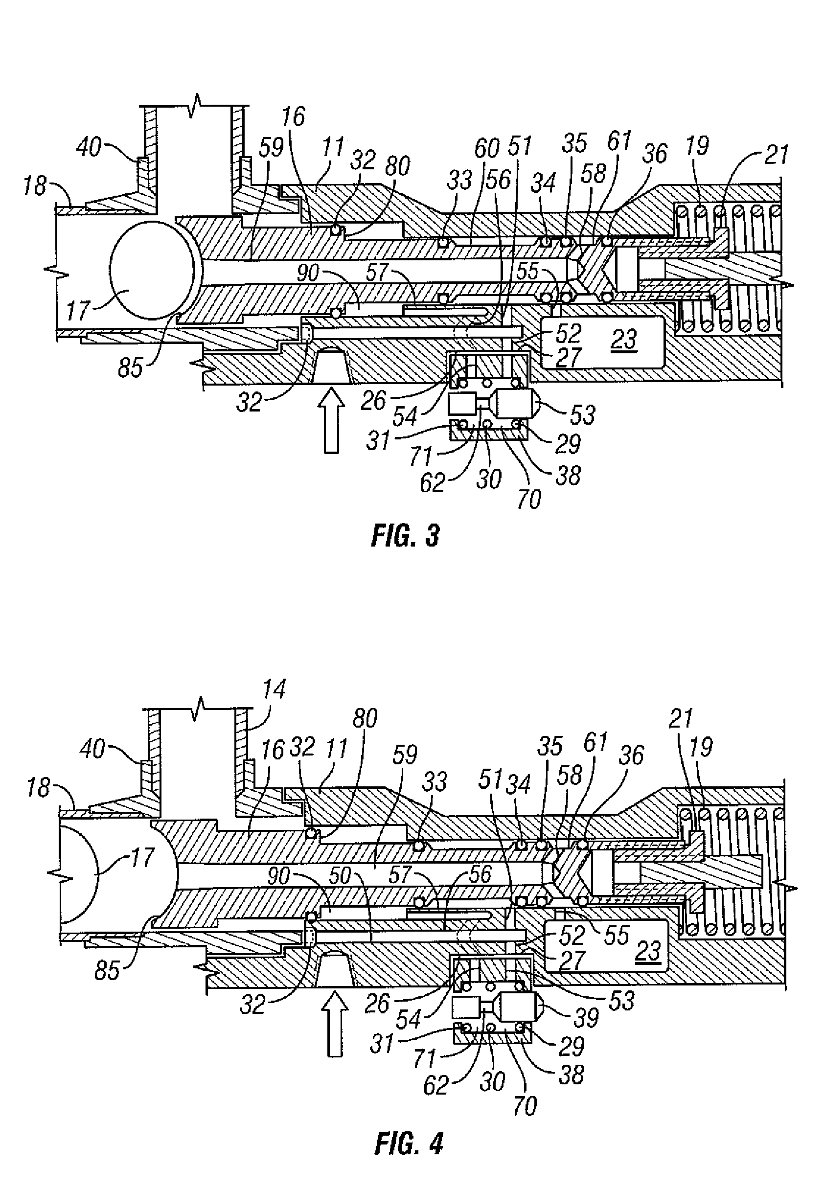
[0048]Referring to FIGS. 1 through 3, paintball gun comprises a bolt 16 having a proximal end and a distal end and defining a firing passageway 59 from a discharge inlet 58 in the proximal end to a discharge outlet 85 in the distal end. The body 11 defines a receptacle for receiving the bolt, a firing charge storage chamber 23 adjacent to but separate from the bolt receptacle, a gas inlet port 15, a first passageway between the storage chamber and the receptacle 50 such that the storage chamber 23 communicates with a first opening 55 in the receptacle, a second passageway between the gas inlet 15 and the receptacle such that the gas inlet 15 communi...


PUM


Abstract

A paintball gun system comprises a bolt defining a propellant passageway and a gun body defining the following elements: a receptacle for receiving the bolt, a firing charge storage chamber adjacent to but separate from the bolt receptacle, a gas inlet port, a first passageway between the storage chamber and the receptacle, a second fixed passageway between the gas inlet and the receptacle. The first passageway communicates with a first flow opening into the receptacle and the second passageway communicates with a second flow opening into the receptacle. The bolt is axially movable between a chargeup position and a firing position. In the chargeup position, the bolt and the body together define a confined flow circuit between the first opening and the storage chamber. In the firing position, the bolt and the body together define a confined flow circuit between the storage chamber and the discharge inlet.

Description

CROSS-REFERENCE TO RELATED APPLICATION[0001]This application claims priority from U.S. Provisional Application for Patent No. 60 / 670,372 filed on 12 Apr. 2005.FIELD OF INVENTION[0002]This invention relates to pneumatic marking guns including paintball guns.BACKGROUND OF THE INVENTION[0003]The earliest paintball marking guns were used for marking in forestry and cattle ranching. Paintball marking guns are now more associated with a variety of targeting and simulated battle games (e.g. capture the flag). These guns launch a ball of paint with a frangible shell that is designed to hold the ball shape until striking an object after firing. Upon striking the object, the ball is set to break open leaving a paint spot.[0004]Paintball guns typically employ a firing system powered by compressed gas such as air. Compressed gas is supplied from a supply tank which is mounted to or carried with the gun. The gun systems are equipped with pressure regulators which receive gas from the tank at a r...

Claims


Application Information

Patent Timeline
Patent Type & Authority Patents(United States)
IPC IPC(8): F41B11/00
CPCF41B11/62F41B11/723F41B11/71
Inventor GABREL, STANLEY
Owner KORE OUTDOOR US INC
Learn More