
Atomizing nozzle structure of high-temperature high-voltage air flow dyeing machine and control method thereof

An airflow dyeing machine, high temperature and high pressure technology, applied in the direction of liquid/gas/steam jet propulsion fabric, textile material treatment, textile processing machine accessories, etc., can solve the problem of large pollution, insufficient level dyeing, liquor ratio of overflow dyeing machine major issues

Inactive Publication Date: 2012-05-23
高勋绿色智能装备(广州)有限公司
View PDF1 Cites 1 Cited by
  • Summary
  • Abstract
  • Description
  • Claims
  • Application Information

AI Technical Summary

Problems solved by technology

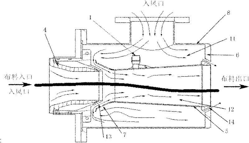
[0006] The main purpose of the present invention is to overcome the shortcomings and deficiencies of the prior art, to provide a high-temperature and high-pressure airflow dyeing machine atomization nozzle structure and its control method, which can solve the problem of large liquor ratio, large pollution, and energy consumption in overflow dyeing machines. High, large sewage discharge and other key technical problems, and can better solve the problems of insufficient level dyeing and cloth blocking in the nozzle structure of the existing air flow dyeing machine

Method used


Image

  • Atomizing nozzle structure of high-temperature high-voltage air flow dyeing machine and control method thereof
  • Atomizing nozzle structure of high-temperature high-voltage air flow dyeing machine and control method thereof
  • Atomizing nozzle structure of high-temperature high-voltage air flow dyeing machine and control method thereof

Examples


Embodiment

[0083] Generally speaking, the high temperature and high pressure airflow dyeing machine is mainly composed of the following components:

[0084] (1) The basic configuration includes: main cylinder body, reserve cylinder, feeding cylinder, material barrel II, material barrel I, heat exchanger, cloth outlet device, cloth lifting device, cloth guiding pipe arrangement device, tank washing device, fan, gas Filters, High Temperature Discharge Mixers, Soda Mixers, Pressure Transmitters, Differential Pressure Transmitters, Floats.

[0085] (2) Pumps and valves: feeding pump I, feeding pump II, main circulation pump, drainage and air supply valve, dye liquor circulation valve, feeding valve before the pump, feeding valve at the bottom of the tank, shut-off valve at the main pump port, horizontal check Valve, volume sensor water inlet valve, high temperature discharge cooling valve, high temperature mixed discharge valve, master vat drain valve II, master vat drain valve I, master vat...


PUM


Abstract

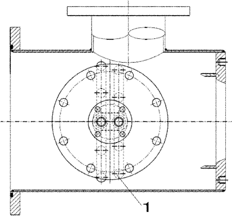
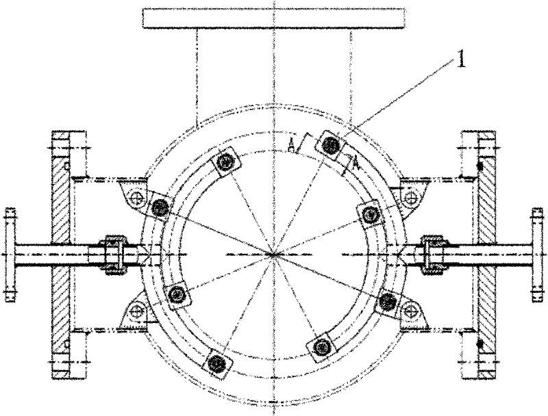
The invention discloses an atomizing nozzle structure of a high-temperature high-voltage air flow dyeing machine and control method thereof. The nozzle structure comprises a front nozzle cover, an inner main stream pipe, a rear nozzle head and a sleeve, wherein the sleeve is sleeved outside the inner main stream pipe, and two ends of the sleeve are respectively connected with the front nozzle cover and the rear nozzle head through a connecting piece; the sleeve is provided with an air inlet which is connected with a fan; and the sleeve and the inner main stream pipe form a circular outer chamber atomizing region; a nozzle head is arranged in the outer chamber atomizing region and is fixed on the outer wall of the inner main stream pipe, and the nozzle head is connected with a dye liquid pipeline; and the outer chamber atomizing region is provided with two outlets which are connected with a channel through which the cloth to be dyed passes in the inner main stream pipe. The invention also provides a control method based on the atomizing nozzle structure of the high-temperature high-voltage air flow dyeing machine. According to the types of the cloth to be dyed, the number of the nozzle heads started in the nozzle structure, the flow rate of the nozzle heads, the air flow of the fan and the temperature process curves adopted are defined. According to the invention, the levellingproperty is high, and the problem of cloth blocking can not happen.

Description

technical field [0001] The invention belongs to the field of dyeing machine design, and in particular relates to an atomizing nozzle structure and a control method of a high-temperature and high-pressure airflow dyeing machine. Background technique [0002] The atomized air-flow dyeing machine is a new process and new technology. Since 1982, similar equipment has been introduced from abroad to my country. There are several domestic manufacturers using this process. At present, the domestic manufacturing technology of this equipment is immature and the technology is relatively difficult. There are many technical issues that need to be improved. Compared with the traditional overflow dyeing machine, the atomized air-flow dyeing machine has a significant advantage of a smaller bath ratio (3 kg of water for 1 kg of cloth is called the bath ratio, and the traditional one is more than 1:7). [0003] At present, dyeing machines are mainly divided into two types according to the dye...

Claims


Application Information

Patent Timeline
Patent Type & Authority Patents(China)
IPC IPC(8): D06B23/00D06B1/08D06B3/28
CPCD06B3/28
Inventor 黎嘉球廖少委
Owner 高勋绿色智能装备(广州)有限公司
Learn More