
Hearth temperature area airflow heat insulation device for mesh belt-free silicon battery plate sintering furnace

A technology of silicon cells and heat insulation devices, applied in the direction of electrical components, furnaces, circuits, etc., can solve the problems of energy waste, large floor space, and large power consumption, so as to reduce production costs, reduce heat consumption, and improve The effect of sintering efficiency

Inactive Publication Date: 2011-05-18
EGING PHOTOVOLTAIC TECHNOLOGY CO LTD
View PDF7 Cites 6 Cited by
  • Summary
  • Abstract
  • Description
  • Claims
  • Application Information

AI Technical Summary

Problems solved by technology

If it is reduced, the furnace temperature zone of the mesh-belt tunnel sintering furnace is not clear, which cannot meet the requirements of the sintering process
In addition, the high temperature-resistant mesh belt needs to circulate around the inside and outside of the furnace during operation. The mesh belt part is accompanied by the heating and cooling process of the silicon wafer. Therefore, during the operation, the mesh belt will carry a large amount of heat from the furnace. Heat, and this part of the heat will all be lost, which not only causes a lot of energy waste, but also increases the temperature of the working environment
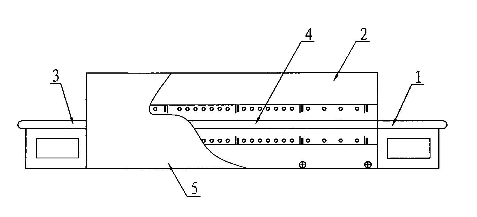
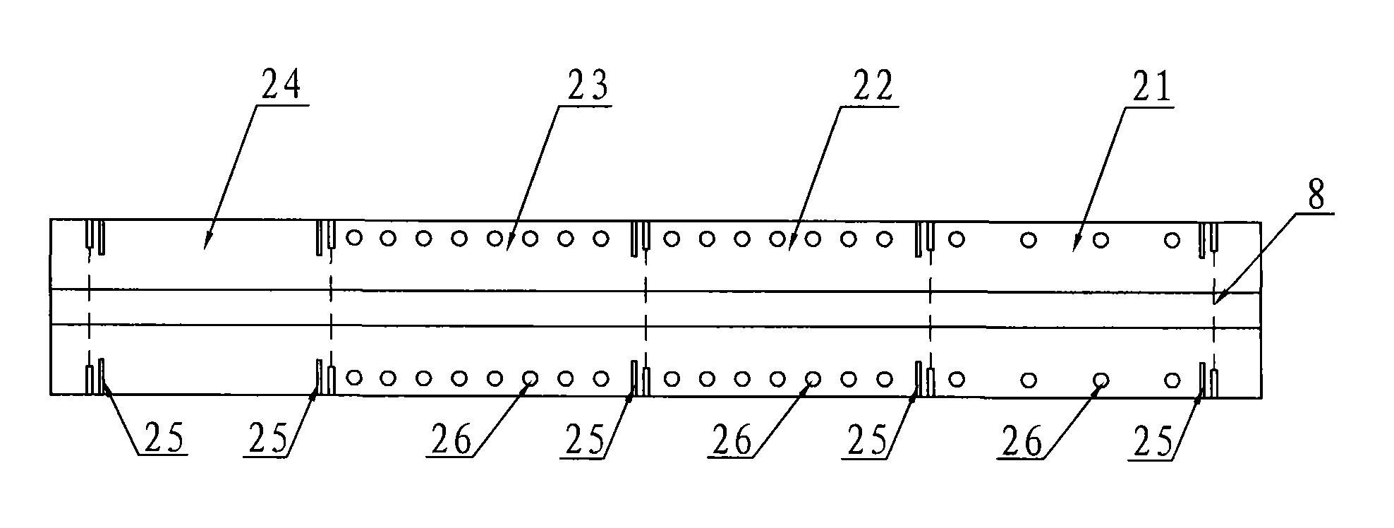
[0004] The applicant has developed a high-efficiency sintering furnace without a mesh belt, which includes a feed table 1, a tunnel-type sintering box 2, a discharge table 3, a silicon wafer conveying device 4 and a furnace frame 5, such as figure 1 As shown, along the longitudinal direction of the tunnel-type sintering box 2, there are four regions successively provided with a preheating debinding area 21, a heating area 22, a sintering area 23, and a cooling area 24. 23 and the cooling zone 24 are provided with a heat shield 25, and a heating element 26 is arranged in the preheating debinding zone 21, the heating zone 22 and the sintering zone 23, such as figure 2 As shown; it can well overcome the disadvantages of the mesh belt sintering furnace, such as large floor area, low thermal efficiency, and large power consumption. Furnace thermal efficiency, the key technology to reduce consumption

Method used


Image

  • Hearth temperature area airflow heat insulation device for mesh belt-free silicon battery plate sintering furnace
  • Hearth temperature area airflow heat insulation device for mesh belt-free silicon battery plate sintering furnace
  • Hearth temperature area airflow heat insulation device for mesh belt-free silicon battery plate sintering furnace

Examples


Embodiment Construction

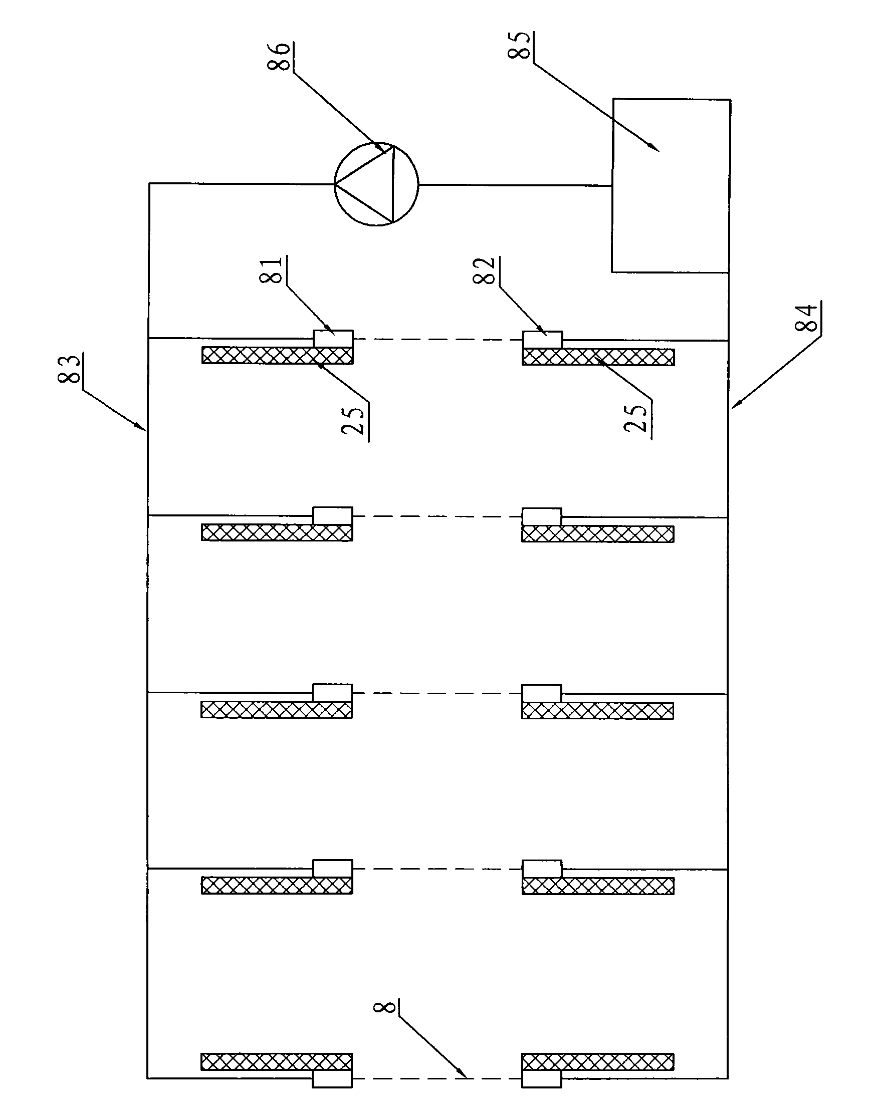
[0014] The air flow heat insulation device in the furnace temperature zone of the non-mesh belt silicon cell sintering furnace, figure 1 , figure 2 , image 3 As shown, it includes a preheating debinding area 21, a heating area 22, a sintering area 23 and a cooling area 24, and is separated by a heat insulating board 25 between each area. Air flow cut-off door 8 is all provided with between cooling zone 24, and is close to insulation plate 25, and air flow cut-off door 8 is made of jet pipe 81, suction pipe 82, intake pipe 83, suction pipe 84, air flow chamber 85 and circulation Pump 86 is made up of, jet pipe 81 and suction pipe 82 are all perpendicular to the direction of the tunnel and correspondingly arranged, and all jet pipes 81 are connected with intake pipe 83, and all suction pipes 82 are connected with suction pipe 84, and intake pipe 83, suction pipe Trachea 84 links to each other with airflow chamber 85, and circulation pump 86 is arranged on the outlet of airfl...


PUM


Abstract

The invention discloses a hearth temperature area airflow heat insulation device for a mesh belt-free silicon battery plate sintering furnace. Heat insulation plates and airflow partition doors are arranged among a preheating glue discharge area, a heating area, a sintering area and a cooling area; the airflow partition door comprises air injection pipes, pumping pipes, an air inlet pipe, an air suction pipe, an airflow accommodating cavity and a circulating pump; both the air injection pipes and the pumping pipes are correspondingly arranged vertical to the direction of a tunnel; and all the air injection pipes are communicated with the air inlet pipe, all the pumping pipes are connected with the air suction pipe, the air injection pipes are communicated with the air outlet of the circulating pump through the air inlet pipe, and the pumping pipes are connected with the air inlet of the circulating pump through the air suction pipe. Because the heat insulation plates and the airflow partition doors are arranged among the areas, a hot air barrier is formed through the pressure difference of the air injection pipes and the pumping pipes, the temperature areas can be effectively partitioned, the temperature in each temperature area is closer to the requirement of a sintering process, the sintering area of the tunnel is isolated with the atmosphere, the sintering efficiency is improved, the heat consumption of the sintering furnace is reduced, and the length of the furnace body of the whole sintering furnace is shortened.

Description

Technical field: [0001] The invention relates to a silicon cell sintering furnace, in particular to a heat insulation structure among the preheating and debinding area, the heating area, the sintering area and the cooling area in the silicon cell sintering furnace. Background technique: [0002] In the production process of solar cells, sintering is a crucial step to make the crystalline silicon substrate truly have the function of photoelectric conversion. Therefore, the performance of the sintering equipment directly affects the quality of the cell. [0003] At present, solar cell manufacturers at home and abroad mainly use sintering furnaces produced by European and American companies. The structure of this type of sintering furnace is a mesh-belt tunnel sintering furnace. In the longitudinal direction of the sintering furnace, there are preheating and debinding areas and heating areas. , sintering area and cooling area, arrange heating lamps of different densities in di...

Claims


Application Information

Patent Timeline
Patent Type & Authority Applications(China)
IPC IPC(8): F27B9/30H01L31/18
CPCY02P70/50
Inventor 孙铁囤荀建华刘志刚高玉山潘盛姚伟忠陈琼
Owner EGING PHOTOVOLTAIC TECHNOLOGY CO LTD
Learn More