
Method for coating film on solar high-temperature heat collection tube used for power generation and horizontal film coating machine

A technology of heat collecting tubes and solar energy, which is applied in the field of vacuum coating special equipment, can solve the problems of difficult maintenance, high equipment, high workshop, etc., and achieve the effect of compact production cycle, good quality and saving auxiliary working time

Inactive Publication Date: 2011-05-11
湖南菲尔姆真空设备有限公司
View PDF7 Cites 10 Cited by
  • Summary
  • Abstract
  • Description
  • Claims
  • Application Information

AI Technical Summary

Problems solved by technology

[0005] The technical solution for realizing the above-mentioned purpose of the present invention is: a method for coating a solar high-temperature heat collector tube for power generation, changing the coating vacuum chamber of a vertical structure into a coating vacuum chamber of a horizontal structure, and the vacuum chamber adopts a cylindrical horizontal top-opening door structure, In order to solve the problems of super high equipment, super high factory building and difficult maintenance caused by super long tube coating

Method used


Image

  • Method for coating film on solar high-temperature heat collection tube used for power generation and horizontal film coating machine
  • Method for coating film on solar high-temperature heat collection tube used for power generation and horizontal film coating machine
  • Method for coating film on solar high-temperature heat collection tube used for power generation and horizontal film coating machine

Examples


Embodiment Construction

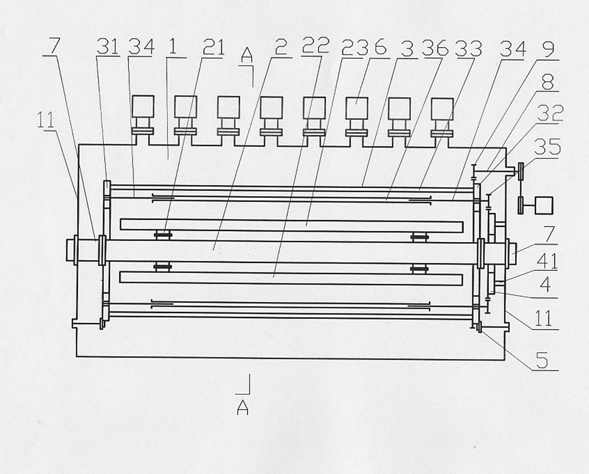
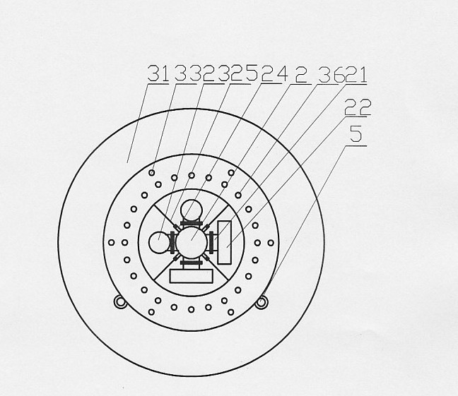
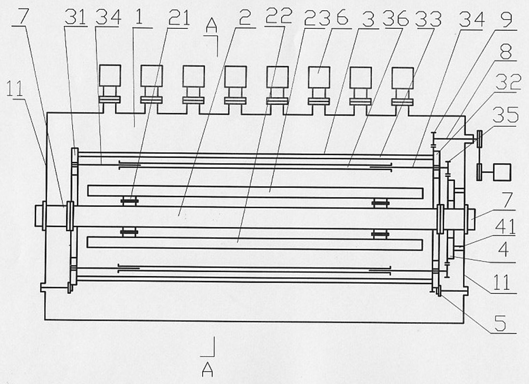
[0022] Such as figure 1 , 2 Shown: a horizontal coating machine for solar high-temperature heat collector tubes for power generation, including a cylindrical vacuum chamber 1 with a horizontal top-opening door structure, a target installation pipe 2, a workpiece rack 3, a fixed toothed plate 4, a support wheel 5 and a rotating drive mechanism , the vacuum chamber 1 is evenly distributed with multiple sets of independent vacuum pumping devices 6 in the length direction. The flange 21 is equipped with a planar magnetron target 22 or / and a rotating cylindrical magnetron target 23, and a partition plate 25 is installed on the target installation pipe fitting 2 through a partition seat 24 to reasonably separate the targets and avoid crossing. pollution, the separator 25 adopts a loose-leaf pluggable structure; the workpiece rack 3 is a rotatable workpiece rack that can be hoisted as a whole, and is placed on four support wheels 5. The left and right rotation shafts 34 are compose...


PUM


Abstract

The invention discloses a horizontal film coating machine for a solar high-temperature heat collection tube used for power generation. The horizontal film coating machine comprises a vacuum chamber 1, a target installment tube 2, a workpiece frame 3, a fixed fluted disc 4, a support wheel 5 and a rotary driving mechanism, wherein the vacuum chamber has a cylindrical and horizontal structure with a door at the upper part, the target installment tube 2 is installed on the left and right side plates 11 in the vacuum chamber 1 through left and right flanges 7 and provided with a planar magnetron sputtering target 22 or / and a rotary cylindrical magnetron sputtering target 23; the workpiece frame 3 consists of a turntable 31, a fluted disc 32, a connecting rod 33 and left and right telescopic autorotating shafts 34; a fixed gear 4 is fixed on the right side plate 11 of the vacuum chamber 1 through support columns 41; and the rotary driving mechanism comprises a power input shaft 8 and a driving gear 9 connected with the power input shaft 8, wherein the driving gear 9 is engaged with the turntable 31. By changing a vertical structure into a horizontal structure, the invention solves the problems on ultrahigh equipment, ultrahigh workshops, use and maintenance and the like caused by the film coating of an overlength tube. The horizontal film coating machine is convenient and reliable to operate, has no oil or gas pollution, and better ensures the quantity of a coated film.

Description

technical field [0001] The invention relates to a special equipment for vacuum coating, in particular to a coating method and a horizontal coating machine for solar high-temperature heat-collecting tubes for power generation. Background technique [0002] At present, the most common heat collector tube coating machines in the domestic market are all vertical structures. The length of the medium and low temperature heat collector tubes produced is mostly within 1.5-2.1 meters. The structure is double-layer single-ended opening, and water is used as the heat transfer medium. The temperature requirement is not high, and it is mainly used in solar water heaters and other hot water projects, which cannot meet the needs of high-temperature heat collecting tubes for solar power generation. The structure of the high-temperature vacuum heat collector tube for power generation is a double-layer double-ended opening. It is coated with a light-selective absorption coating on an alloy tu...

Claims


Application Information

Patent Timeline
IPC IPC(8): C23C14/35
Inventor 李云辉李云松华冬辉
Owner 湖南菲尔姆真空设备有限公司
Learn More