
A circular planar magnetron sputtering target with rotating magnetic poles

A magnetron sputtering and magnetic pole technology, which is applied in sputtering coating, metal material coating process, vacuum evaporation coating, etc., can solve the problem of low utilization rate of target materials, and achieve the goal of improving utilization rate and sputtering rate Effect

Active Publication Date: 2022-04-15
HUNAN CITY UNIV
View PDF7 Cites 0 Cited by
  • Summary
  • Abstract
  • Description
  • Claims
  • Application Information

AI Technical Summary

Problems solved by technology

Under this magnetic field layout, etching grooves are formed on the surface of the target during the sputtering process, resulting in only the target in the etching groove being sputtered on the entire circular planar target, so the traditional circular planar magnetron sputtering The target utilization rate of the target is low
[0005] Therefore, there is a need for a circular planar magnetron sputtering target with rotating magnetic poles, which can solve the problem in the prior art that only the target in the etching groove is sputtered and the target utilization rate is low

Method used


Image

  • A circular planar magnetron sputtering target with rotating magnetic poles
  • A circular planar magnetron sputtering target with rotating magnetic poles
  • A circular planar magnetron sputtering target with rotating magnetic poles

Examples


Embodiment 1

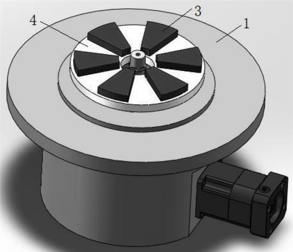
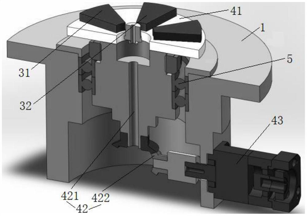
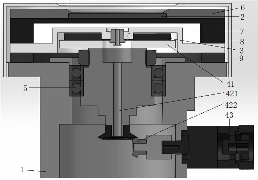
[0044] like figure 1 , figure 2 and image 3 shown.

[0045] This embodiment is a circular planar magnetron sputtering target with rotating magnetic poles, including:

[0046] Target base 1, which is a hollow cylindrical structure;

[0047] The magnetic pole rotation system 4 is arranged on the target base 1 and is movably connected with the target base 1; the magnetic pole rotation system 4 is a rotatable cylindrical structure, and the magnetic pole rotation system 4 is coaxial with the target material 2;

[0048] The magnetic pole 3 is arranged on the magnetic pole rotation system 4 and driven to rotate by the magnetic pole rotation system 4 .

[0049] With such a structure, the present invention places a plurality of magnetic poles 3 evenly distributed along the radial direction of the magnetic pole rotation system 4, so that the magnetic induction lines are arranged along the circumferential direction of the target material 2, and the magnetic poles 3 can be rotated; ...


PUM


Abstract

The invention provides a circular planar magnetron sputtering target with magnetic pole rotation, comprising: a target base, which is a hollow cylindrical structure; a magnetic pole rotation system, which is arranged on the target base and is movable with the target base. connection; the magnetic pole rotation system is a rotatable structure; the magnetic pole is set on the magnetic pole rotation system and driven to rotate by the magnetic pole rotation system. In the present invention, a plurality of magnetic poles are evenly distributed along the radial direction of the magnetic pole rotation system, so that the magnetic induction lines are arranged along the circumferential direction of the target, and the magnetic poles in the present invention can be rotated, thereby preventing the formation of obvious etching grooves on the surface of the target and improving the The utilization rate of the target and the sputtering rate are improved, thereby solving the deficiencies in the prior art.

Description

technical field [0001] The invention specifically relates to a circular planar magnetron sputtering target with rotating magnetic poles. Background technique [0002] Reference document: Chinese Invention Patent Publication CN102719799A, publication date 20121010, discloses a rotating magnetron sputtering target and a corresponding magnetron sputtering device, the rotating magnetron sputtering target includes a cylindrical target, a pole piece and a magnetic The magnetron includes a first magnetic pole arranged in the middle of the magnetron and second magnetic poles arranged on both sides of the magnetron, and the polarities of the first magnetic pole and the second magnetic pole are opposite. [0003] In the rotating magnetron sputtering target in the reference file, the magnetic field is distributed along the cylindrical surface in the circumferential direction of the rotating cylinder, which belongs to the rotating cylindrical target. However, in practical applications,...

Claims


Application Information

Patent Timeline
Patent Type & Authority Patents(China)
IPC IPC(8): C23C14/35
CPCC23C14/35
Inventor 朱国刘文玉
Owner HUNAN CITY UNIV
Learn More