
Loudspeaker and vibration part thereof

A technology of vibrating components and loudspeakers, applied in the direction of sensors, electrical components, etc., can solve problems such as limitation of loudspeaker sound effects, impact on magnets, limitations, etc., and achieve the effects of improving the utilization efficiency of magnetic circuits, improving sensitivity, and high withstand power

Active Publication Date: 2013-07-24
CHANGZHOU SOUND DRAGON ELECTRONICS & ACOUSTICS
View PDF3 Cites 0 Cited by
  • Summary
  • Abstract
  • Description
  • Claims
  • Application Information

AI Technical Summary

Problems solved by technology

[0006] (1) For the magnetic circuit part of the speaker, in order to obtain a better bass effect, the magnet must be as large as possible, and a large magnet needs a large voice coil to cooperate, and the use of a large voice coil often limits the use of traditional positioning devices
(2) In order to obtain a better bass effect, it is necessary to use a composite edge paper cone, which is easily deformed in the radial direction, so that the radial movement of the voice coil cannot be well restricted
(3) For the vibration part of the speaker, if an extra-long racetrack-shaped voice coil is used and no positioning support is used, the voice coil is prone to deformation
(4) For ultra-thin speakers, if the positioning support piece is not used, since the voice coil cannot be limited or positioned during the movement, its axial movement range is not easy to be limited, and the voice coil is easy to hit the bottom during the axial movement , and at the same time, radial shaking is more likely to occur, which will cause abnormal noise when hitting the magnet, pole piece or magnetic cover
[0007] According to the above, it can be concluded that for the magnetic circuit part and vibration part of an ultra-long, ultra-narrow, and ultra-thin speaker, if an ultra-long voice coil and a large magnet are to be used to achieve the required performance, there will be no external coils. Installing a traditional positioning device in the space will limit the pronunciation effect of the speaker, and also cause abnormal pronunciation because the voice coil cannot be limited.

Method used


Image

  • Loudspeaker and vibration part thereof
  • Loudspeaker and vibration part thereof
  • Loudspeaker and vibration part thereof

Examples


Embodiment 1

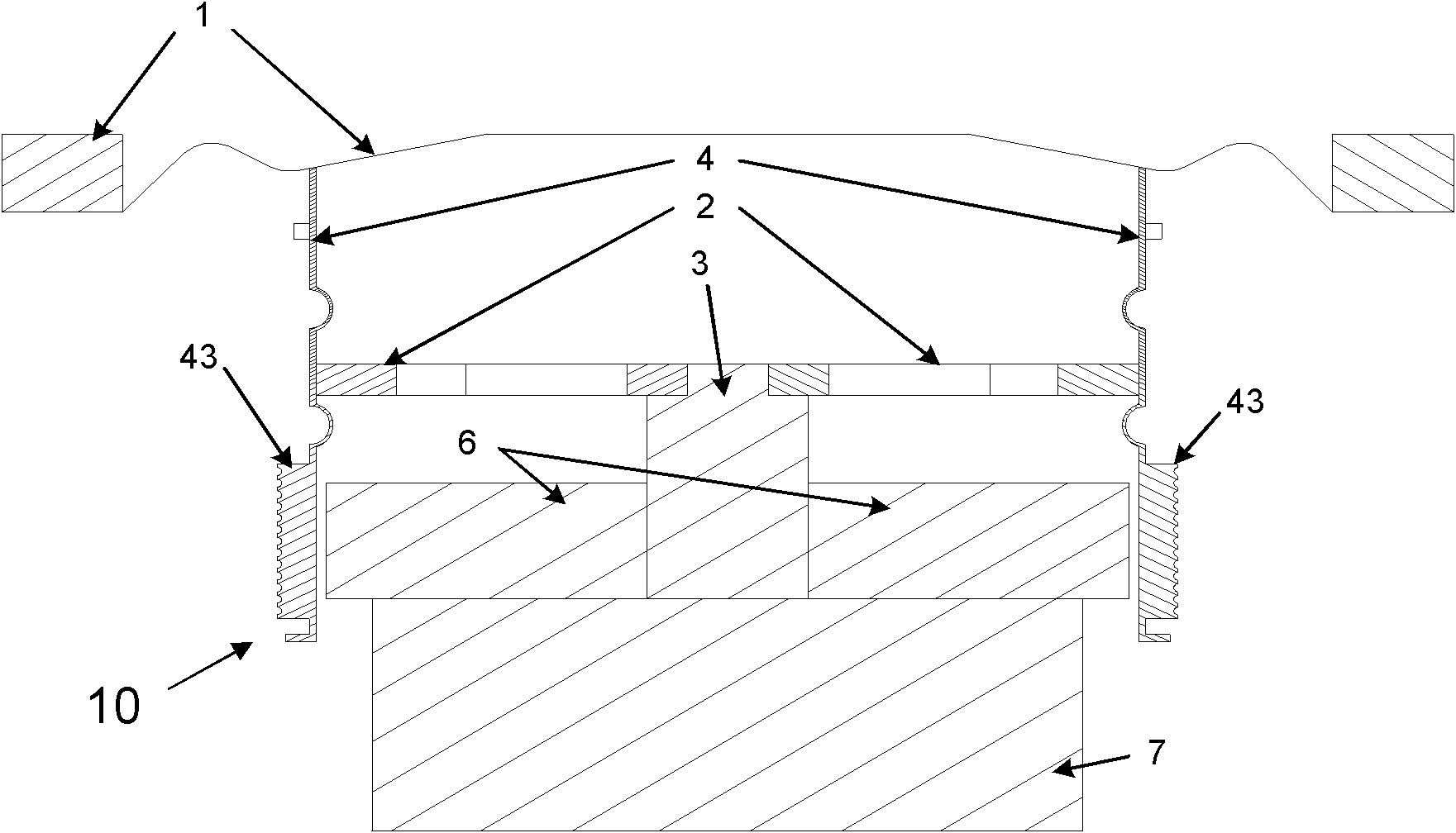
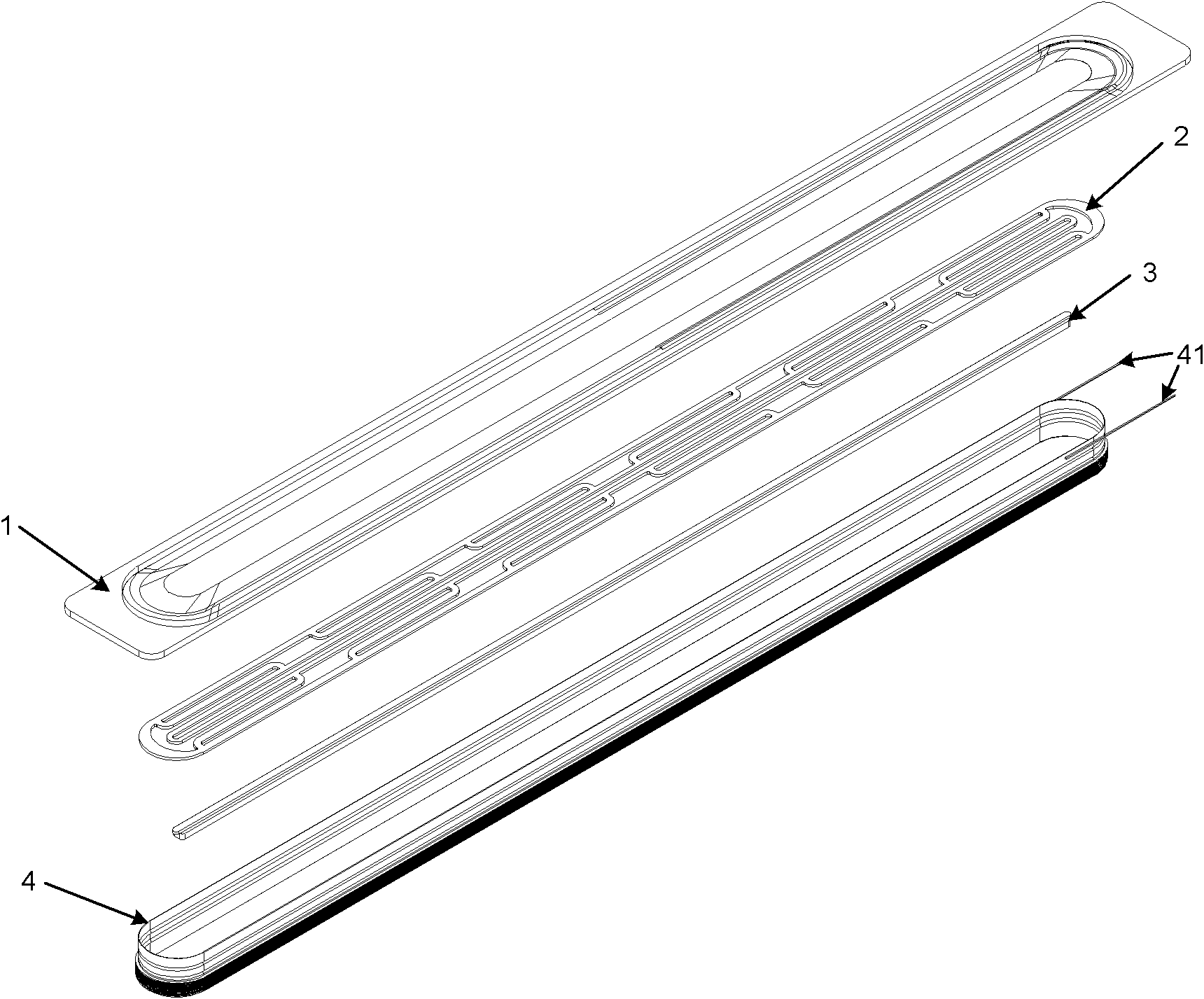
[0027] refer to figure 1 , the vibrating part 10 of the first loudspeaker of the present invention is mainly composed of four parts: a paper cone 1, a positioning strut 2, a bracket 3 and a voice coil 4, and each part will be described below.

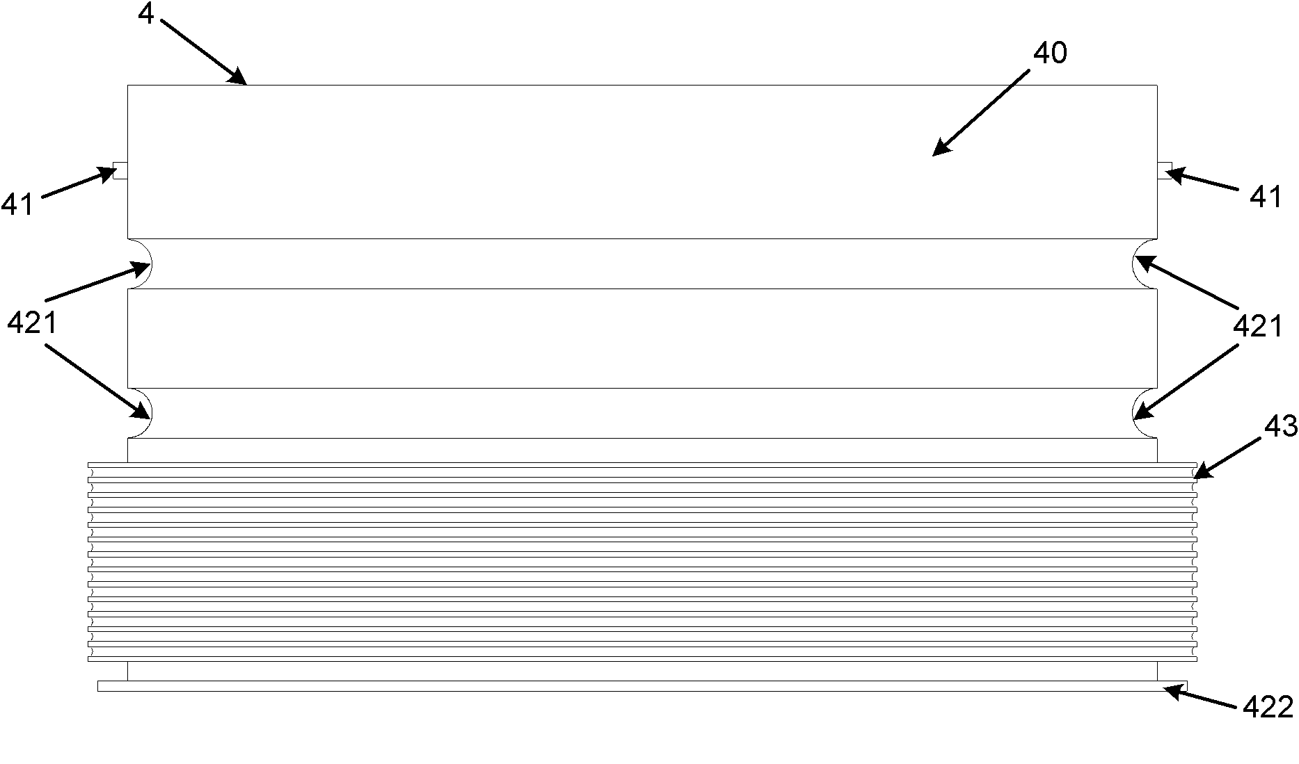
[0028] refer to Figure 1 to Figure 3 , the voice coil 4 and the paper cone 1 are glued and fixed as a whole by means of tooling positioning. The voice coil 4 includes a racetrack-shaped voice coil body 40, and a coil 43 is wound on the outer wall surface of the voice coil body 40. When the voice coil is in operation, a changing current will pass through the coil 43, and the changing current in the magnetic field will be affected. The Lorentz force creates motion, which drives the voice coil. Voice coil lead wires 41 are arranged on the outer wall of the voice coil body 40 , and the lead wires 41 are welded and fixed to the wiring board 9 . Ribs are provided on the side wall of the voice coil body 40 , and the strength of the voice c...

Embodiment 2

[0033] refer to Figure 6 , the voice coil 4 is a circular voice coil, the positioning strut 2 is circular, and the positioning strut includes a plurality of suspension arms 22', and an annular outer ring 21' and an inner ring 23', the suspension arms One end of the suspension arm is connected to the outer ring, and the other end of the suspension arm is connected to the inner ring. In this embodiment, the suspension arm 22' includes an arc-shaped suspension arm main body, an arc-shaped outer ring connecting arm, and an arc-shaped inner ring connecting arm, so that the entire suspension arm 22' is in a "bow" shape. One end of the connecting arm of the outer ring is connected with the outer ring, the other end of the connecting arm of the outer ring is connected with the main body of the suspension arm, one end of the connecting arm of the inner ring is connected with the inner ring, and the other end of the connecting arm of the inner ring is connected with the main body of th...


PUM


Abstract

The invention discloses a vibration part of a loudspeaker, comprising a speech coil and a cone, wherein the cone is fixedly connected with the speech coil; the inside wall of the speech coil is provided with a positioning support chip which is fitted with the inside wall of the speech coil mutually; the lower surface of the positioning support chip is provided with a support for supporting the positioning support chip; and the thickness of the positioning support chip is less than that of the positioning support chip. The vibration part of the loudspeaker uses the positioning support chip to position the speech coil of the vibration part so as to restrict the axial and radial movement ranges of the speech coil, thus improving the performance of the vibration part or the loudspeaker.

Description

technical field [0001] The invention relates to a loudspeaker on audio equipment and its vibrating parts. Specifically, a positioning device is used to position the voice coil of the vibrating part to limit its axial and radial range of motion, so as to improve the performance of the vibrating part or the loudspeaker. Background technique [0002] With the development of electronic technology, the miniaturization of various equipment has become an irreversible trend, and at the same time, the miniaturization of equipment has higher and higher requirements for speaker design. How to improve the performance of the loudspeaker when the thickness and width of the loudspeaker are limited has become the biggest problem for the majority of technicians. [0003] Existing loudspeaker design technology often adopts a design without a voice coil positioning device when there is no space to place a positioning device, which brings many performance limitations, making the designed speake...

Claims


Application Information

Patent Timeline
Patent Type & Authority Patents(China)
IPC IPC(8): H04R9/02H04R9/06
Inventor 谢光宇杨敏
Owner CHANGZHOU SOUND DRAGON ELECTRONICS & ACOUSTICS
Learn More