
Method for calibrating sound phase instrument

A calibration method, calibrator technology, applied in the direction of electrical components, etc., can solve the problems of difficult selection of correlation threshold, time-consuming and labor-intensive calibration work, bulky and cumbersome devices, etc., to achieve the effect of ensuring accuracy and objectivity, small size, simple and reliable method

Inactive Publication Date: 2011-03-23
INST OF ACOUSTICS CHINESE ACAD OF SCI
View PDF2 Cites 5 Cited by
  • Summary
  • Abstract
  • Description
  • Claims
  • Application Information

AI Technical Summary

Problems solved by technology

However, since the structure of the microphone array elements is different during manufacturing and processing, and the assumption of the microphone array elements in the positioning algorithm of digital signal processing is that the electroacoustic characteristics are completely consistent, this error will seriously affect the positioning. , so it is necessary to calibrate the generated sonogram
[0003] The traditional phaser calibration method is to calibrate the microphone array elements one by one by adding a standard sound source to eliminate the difference between the microphone array elements, thus ensuring the correctness of the sound image generated by the panner. However, when the microphone array Calibration becomes time consuming as the number of elements increases
Another method for calibrating the entire pannatron is the fixed reference sound source detection method, which uses a point sound source to emit sound at a specific position for verification and calibration, but this process must be carried out in a specific device, which is An acoustic drum, the walls of which are completely filled with sound-absorbing material of uniform thickness, so the device is very bulky and bulky, not easy to carry, and expensive
Patent 200810213962.X proposes a calibration method, which calculates the acoustic correlation between the audio signal and the noise signal received by each microphone array element, and calculates the average value of the gain when the acoustic correlation exceeds the set correlation threshold to adjust each The gain of the channel achieves the purpose of calibration, but this method has no specific and feasible standards to rely on when setting the correlation threshold, and it is very difficult to select the correlation threshold

Method used


Image

  • Method for calibrating sound phase instrument
  • Method for calibrating sound phase instrument
  • Method for calibrating sound phase instrument

Examples


Embodiment 1

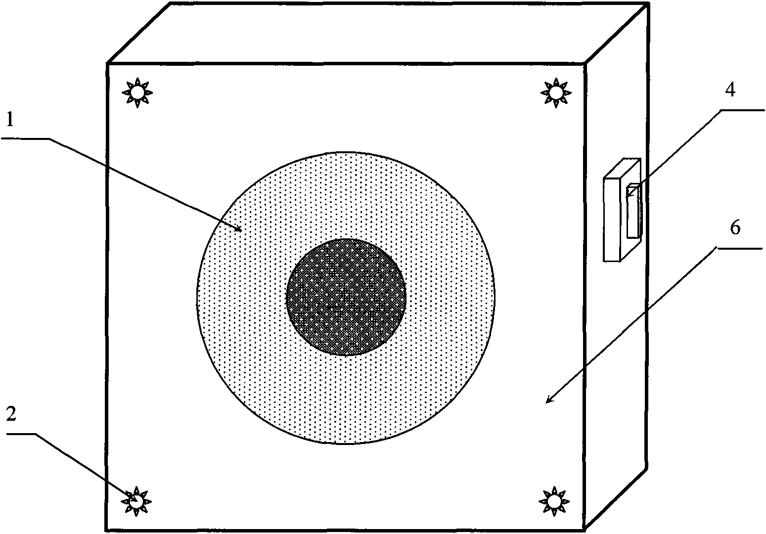
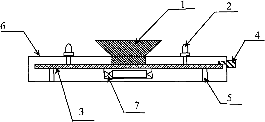
[0055] This embodiment is a panometer calibrator equipped with a calibration light source composed of 4 LED light-emitting diodes, such as Figure 1~2 Shown. The structure includes: single frequency calibration sound source 1, calibration light source 2, circuit board 3, control switch 4, bracket 5, shell 6, battery box 7.

[0056] Such as figure 1 with 2 As shown, the circuit board 3 is fixedly connected to the housing 6 through 4 brackets, the battery box 7 is installed on the back of the circuit board 3, and the single-frequency calibration sound source 1 and the 4 LED light-emitting diodes 2 of the calibration light source are soldered on the circuit board 3. The switch 4 is welded on the circuit board 3 to control the operation of the single-frequency calibration sound source 1 and the calibration light source 2.

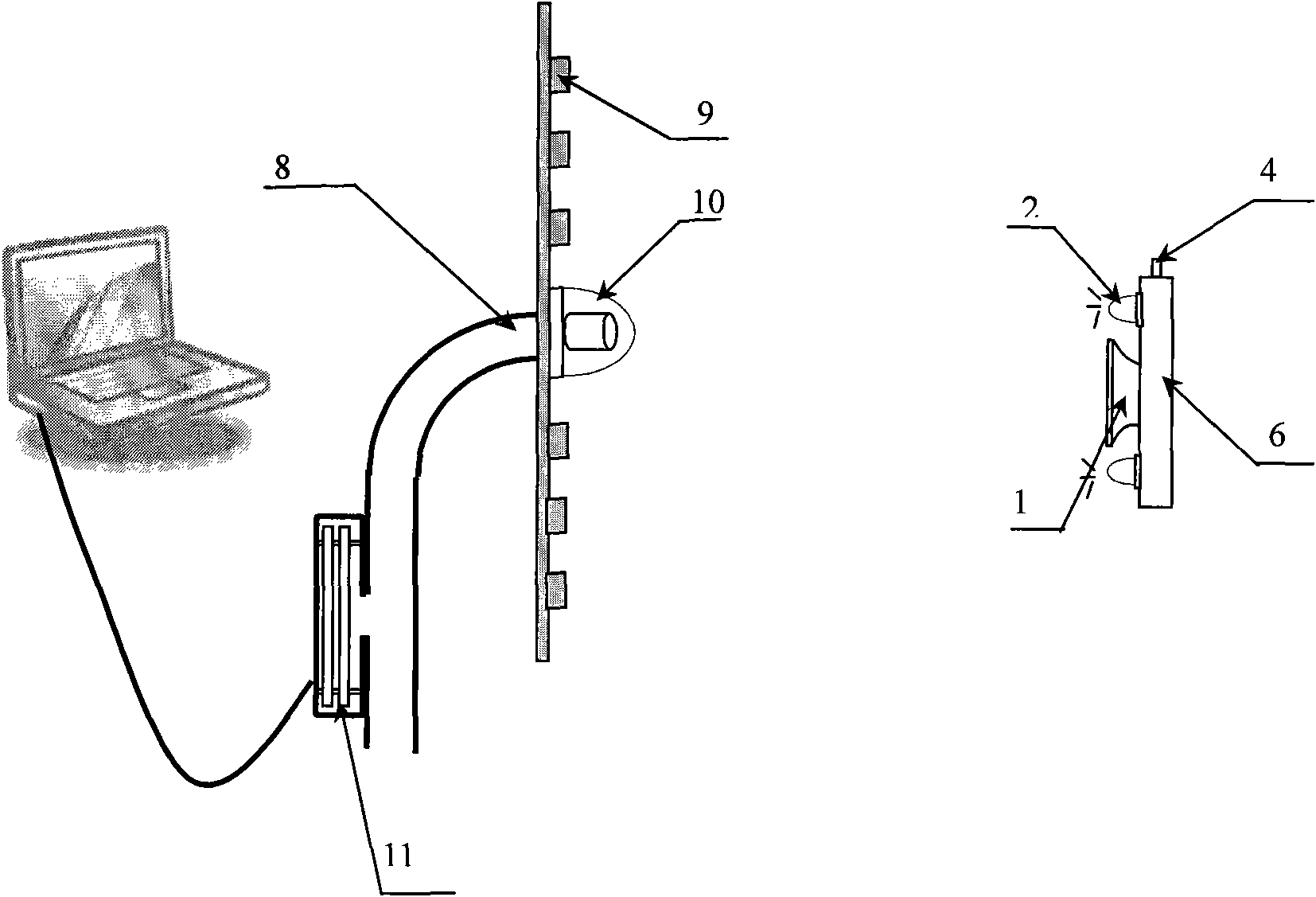
[0057] Such as image 3 As shown, when the switch 4 is pressed, the panometer calibrator starts to work, the single-frequency calibration sound source 1 emits a st...

Embodiment 2

[0070] This embodiment is basically the same as Embodiment 1, except that the verification light source in this embodiment has only one LED light-emitting diode, so the calibrator has a smaller volume and a simpler structure, as shown in FIG. 5. In this way, the calibration calculation process is also simplified, using the position of the LED light-emitting diode (x D , Y D ) As the standard position of the single-frequency calibration sound source, calculate the x-axis offset correction coefficient L x And y-axis offset correction factor L y The formula of is shown in the following formulas (7) and (8):

[0071] L x = X D -X (7)

[0072] L y =y D -Y (8)

[0073] The coordinates of the LED point light source on the screen (x Dj , Y Dj ) j=1, 2,..., N, j represents the label of the calibration position of the calibrator, that is, four positions up, down, left, and right. Calculate the x-axis scaling correction factor K x And y-axis scaling correction factor K y The formula of is ...


PUM


Abstract

The invention relates to a method for calibrating a sound phase instrument, which comprises the steps of: placing sound phase instrument calibrators in front of the sound phase instrument, keeping with a camera in the same line, acquiring sound and optical signals sent by the sound phase instrument calibrators and processing, calculating and storing an x-axis offset correction coefficient Lx and a y-axis offset correction coefficient Ly, placing the sound phase instrument calibrators at top, bottom, left and right positions in front of the sound phase instrument for respectively working, calculating and storing an x-axis scaling correction coefficient Kx and a y-axis scaling correction coefficient Ky, and calibrating the position of a sound image synthesized by real measurement data by using calibration factors of the x-axis offset correction coefficient Lx and the y-axis offset correction coefficient Ly as well as the x-axis scaling correction coefficient Kx and the y-axis scaling correction coefficient Ky. The method is simple and reliable, can be used for rapidly calibrating the offset of the sound phase instrument, and lays the foundation for the accurate work of the sound phase instrument for calibrating the position of the sound image synthesize by the real measurement data.

Description

Technical field [0001] The present invention relates to the field of acoustic measurement, in particular, the present invention relates to a calibration method of a pantograph. Background technique [0002] The positioning of the panning instrument uses its microphone array elements to be arranged in a certain regular shape to collect and convert sound information into digital signals, which are input into the digital signal processor, and beam forming methods are used to realize sound source localization, sound field detection, Eliminate background noise and other functions. However, because the structure of the microphone array element is different during manufacturing and processing, and the assumption of the microphone array element in the digital signal processing positioning algorithm is that the electro-acoustic characteristics are completely consistent, this error will cause serious positioning. Therefore, it is necessary to calibrate the generated sound image. [0003] T...

Claims


Application Information

Patent Timeline
Patent Type & Authority Applications(China)
IPC IPC(8): H04R29/00
Inventor 杨亦春滕鹏晓
Owner INST OF ACOUSTICS CHINESE ACAD OF SCI
Learn More