
Method and device for treating fluorine-containing waste water

A treatment method and technology of a treatment device, which are applied in the field of environmental engineering, can solve the problems of large influence of fluoride ion removal, difficulty in maintaining lasting production, stable operation, and narrow range of pH value requirements.

Inactive Publication Date: 2011-01-12
CENT SOUTH UNIV
View PDF1 Cites 45 Cited by
  • Summary
  • Abstract
  • Description
  • Claims
  • Application Information

AI Technical Summary

Problems solved by technology

In actual operation, colloidal CaF is easily produced during lime neutralization and precipitation. 2 , so that the method has the following problems: (a) colloidal CaF 2 Sedimentation and sedimentation are difficult to separate, making the effluent F - The concentration is unstable, usually F in the wastewater after treatment - It can only be reduced to 20-30mg / L, which cannot meet the requirements of the first-level standard of GB8979-96 "Integrated Wastewater Discharge Standard"; (b) CaF 2 The sediment has a high moisture content and cannot be recycled as a product, and it is easy to cause secondary pollution after storage
This method has a good defluorination effect, but there are the following problems: (a) the process requires a narrow range of pH value at the dosing point, and the fluoride ion removal effect is greatly affected by operational factors such as stirring conditions and settling time, making production It is difficult to maintain long-term and stable operation; (b) Due to the loose flocs, the sludge clarification time is longer, the sludge volume is large, the moisture content is high, and the cost of flocculants is high, which affects the wide application of this method

Method used


Image

  • Method and device for treating fluorine-containing waste water
  • Method and device for treating fluorine-containing waste water
  • Method and device for treating fluorine-containing waste water

Examples


Embodiment approach 1

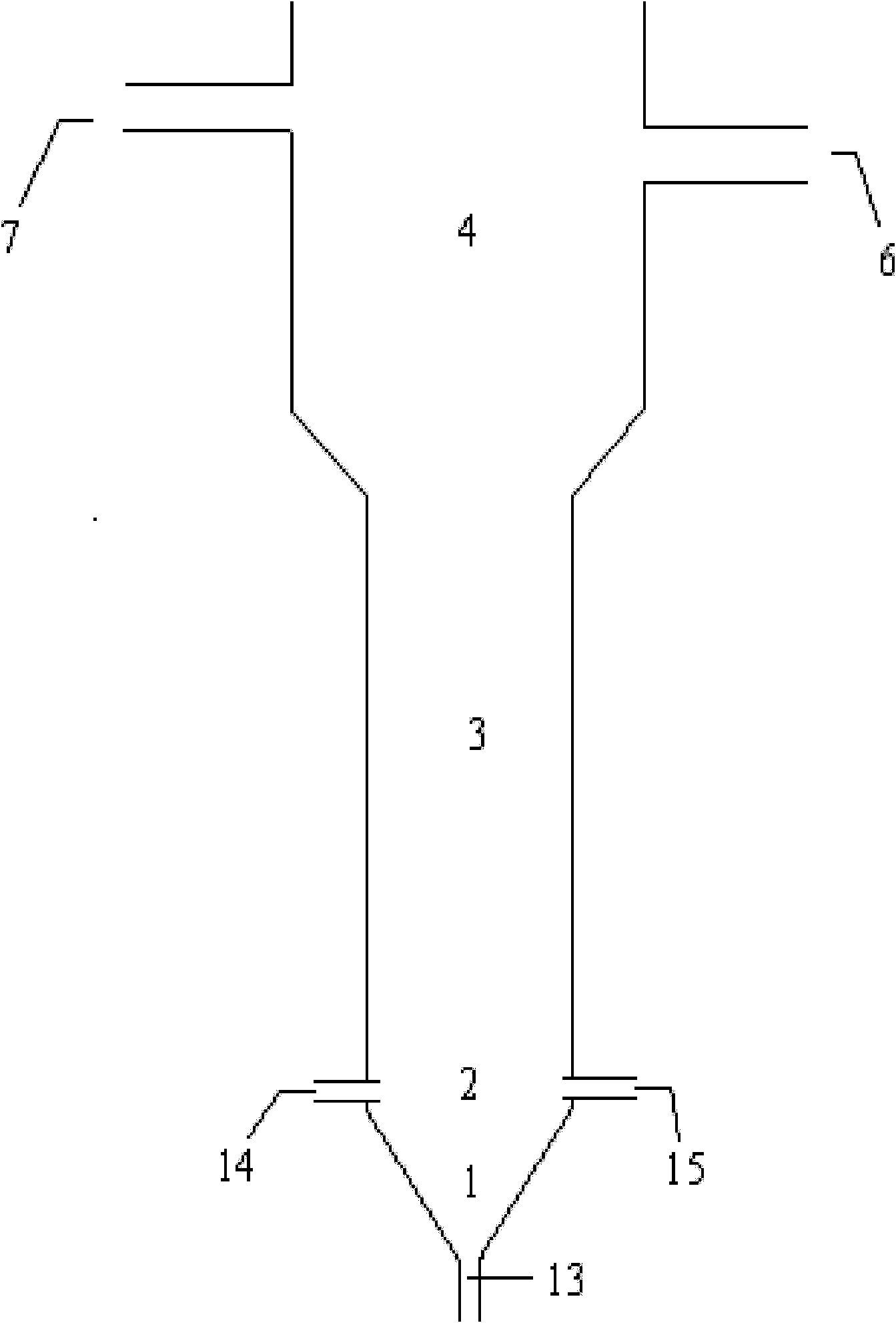
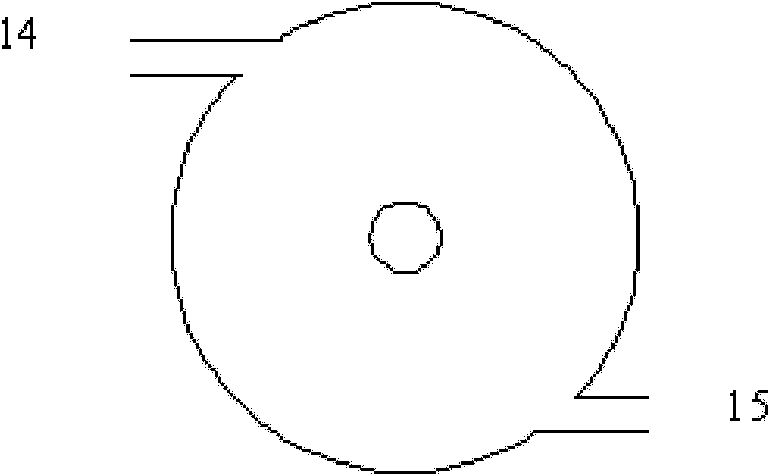
[0028] Embodiment 1: Combining figure 1 , figure 2 Explain the structure of the treatment device, which is mainly composed of calcium fluoride sludge settlement area 1, fluorine-containing wastewater-calcium-containing precipitant mixing area 2, fluidized crystallization area 3, solid-liquid separation area 4, fluorine-containing wastewater and calcium-containing precipitation The agent is added through the fluorine-containing wastewater inlet pipe 14 and the calcium-containing precipitating agent inlet pipe 15 respectively, and is treated by fluidized bed crystal seed crystallization and precipitation; coarse particles settle into the calcium fluoride sludge settlement area, and some fine particles of calcium fluoride enter the solid-liquid Separation zone: fine-grained calcium fluoride is settled and separated in the solid-liquid separation zone, part of the effluent (i.e. primary treatment water) flows back into the calcium-containing precipitant inlet pipe 15 through the ...

Embodiment approach 2

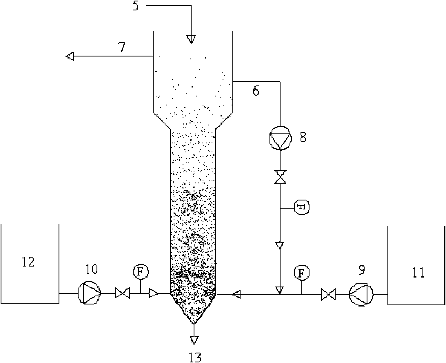
[0029] Embodiment 2: Combining figure 1 , figure 2 , image 3To illustrate the fluorine-containing wastewater treatment process, a certain amount of calcium fluoride seeds with a particle size of 10 μm-100 μm is added to the treatment device from the top inlet 5 of the cylindrical fluidized bed body, and the calcium-containing precipitant water tank 11 and the fluorine-containing wastewater tank 12 The calcium-containing precipitant and the fluorine-containing wastewater are sent to the fluoride-containing wastewater-calcium-containing precipitant mixing zone 2 through the second water pump 9 and the third water pump 10 according to the reaction ratio, and the influent flow rate is adjusted to maintain the concentration of the calcium fluoride seed crystal. Fluidization, the rising speed of the solution is 0.01-0.05m / s, and the pH of the solution in the fluidized bed is adjusted to 2-5. After fully reacting, the coarse calcium fluoride particles enter the calcium fluoride sl...

Embodiment 1

[0031] see figure 1 , figure 2 , image 3 With Embodiment 1 and Embodiment 2, 150g of calcium fluoride seeds with an average particle diameter of 19 μm are added to a treatment device with a volume of 5L in the fluidized bed reaction zone, and Ca(OH) 2 The supernatant is used as a precipitant, and the volume ratio of the precipitant to the fluorine-containing wastewater is adjusted to be 4:1 (wastewater concentration 3100mg / L, pH=2.94), Ca / F=1.2:2, and the rising speed of the solution is 0.02m / s. Reaction pH to 4.0, discharge calcium fluoride precipitation sludge and dry after reaction, see Figure 4 , it can be seen that the calcium fluoride obtained by the reaction is sandy, the particle size is large, the moisture content of the sediment after filtration is 37%, and the content of calcium fluoride after drying is 96%, which can be reused as raw materials for production, and the primary treatment of water fluoride ions The concentration is 28mg / L. Send the primary treat...


PUM


Abstract

The invention provides a method and a device for treating fluorine-containing waste water. In the method, a solid-liquid fluidized bed is used as a crystal reactor; a certain amount of calcium fluoride seed crystal is added into the reactor; the fluorine-containing waste water and a calcium-containing precipitator are delivered into a treatment device of the solid-liquid fluidized bed in a reacting ratio to ensure that fluorinions are precipitated on the surface of the calcium fluoride seed crystal; the prepared sand-shaped calcium fluoride precipitated slurry after precipitation is reclaimed; and primarily treated water is subjected to flocculent precipitation further to meet the emission standard. By adopting the method, most fluorinions can be precipitated in the crystallization and precipitating process in the fluidized bed, the generated sand-shaped calcium fluoride has low content of water and high content of calcium fluoride and can be used as fluorine resources for recycling; and in the flocculent precipitating process of the primarily treated water, the consumption of the fluorescent is low, and the yield of slurry is low. Therefore, the comprehensive cost for waste watertreatment is low.

Description

Technical field: [0001] The invention belongs to the field of environmental engineering, and relates to a method and a device for precipitating and separating fluorine ions in the form of calcium fluoride from fluorine-containing wastewater, which can effectively remove fluoride ions in wastewater and recycle calcium fluoride precipitation. Background technique [0002] Wastewater discharged from industries such as chemical industry, non-ferrous metallurgy, glass, electronics, and electroplating often contains high concentrations of fluoride, causing fluorine pollution in the water environment. Research on fluorine-containing wastewater treatment technology has always been an important topic in the field of environmental protection at home and abroad. At present, there are mainly lime neutralization precipitation method and coagulation precipitation method in domestic and foreign fluorine-containing industrial wastewater treatment methods. [0003] The lime neutralization pr...

Claims


Application Information

Patent Timeline
IPC IPC(8): C02F1/52C02F1/58C01F11/22C02F101/14
Inventor 周康根姜科李程文杨有才李强
Owner CENT SOUTH UNIV
Learn More