
Method for welding circumferential weld between metal thin-wall clad layer and base layer of clad pipe

A welding method and thin metal technology, applied in the direction of welding medium, welding equipment, welding equipment, etc., can solve problems such as cracks and bad structures, and achieve the effects of ensuring corrosion resistance, increasing effective thickness, and good plastic toughness

Inactive Publication Date: 2010-12-29
SHANGHAI HUGONG ELECTRIC WELDING MACHINE MFG
View PDF2 Cites 23 Cited by
  • Summary
  • Abstract
  • Description
  • Claims
  • Application Information

AI Technical Summary

Problems solved by technology

[0004] The purpose of the present invention is to provide a thin-walled stainless steel clad layer and carbon steel base layer composite pipe girth weld welding method, to solve the technical problems of bimetal composite pipe girth weld welding stainless steel clad layer and carbon steel base layer, to overcome the existing welding The technology is not suitable for the welding of composite pipes with a cladding thickness of less than 2 mm; the use of stainless steel welding materials with the same composition as the cladding will cause a certain amount of martensitic hardening poor structure after the sealing weld is diluted by the base carbon steel, resulting in lack of crack

Method used


Image

  • Method for welding circumferential weld between metal thin-wall clad layer and base layer of clad pipe
  • Method for welding circumferential weld between metal thin-wall clad layer and base layer of clad pipe
  • Method for welding circumferential weld between metal thin-wall clad layer and base layer of clad pipe

Examples


Embodiment 1

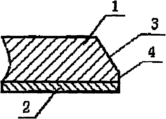
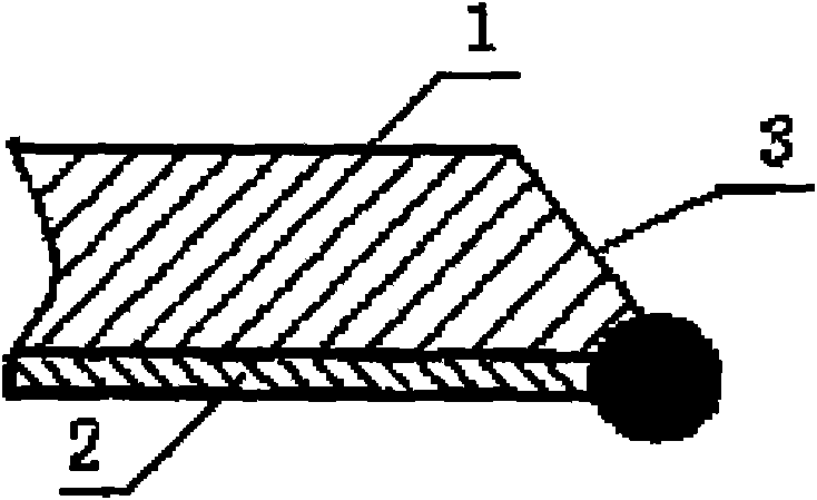
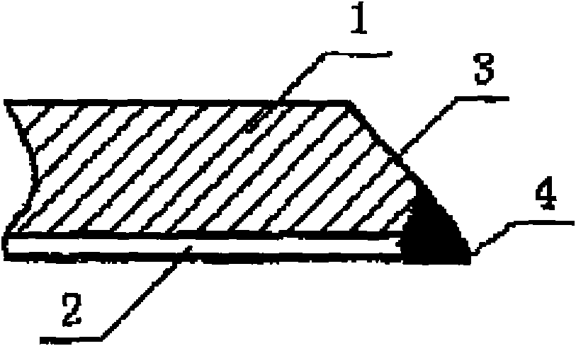
[0024] Embodiment 1: see attached figure 1 . The relative welding of bimetal composite pipes with an outer diameter of 114 mm is taken as an example to illustrate. The thickness of the carbon steel base layer is 12 mm, and the thickness of the stainless steel cladding layer is 1.5 mm.

[0025] (1) Groove processing: use machining method to process a groove with an angle of 30 degrees and a blunt edge of 5 mm at the pipe end. Use a grinding wheel to polish the rust on the carbon steel near the groove, and clean the oil on the groove with acetone.

[0026] (2) Sealing welding: Surfacing 2-3 layers of stainless steel on the groove close to the inner surface of the bottom sealing bead. The welding method is argon tungsten arc welding, using 309Mo type austenitic stainless steel wire, the model is ER309MoI. , the grade is HOOCr24Ni13M02, and the diameter is 2 mm. After welding, use a grinding wheel to grind the groove, the angle is 30-35 degrees, and the blunt edge is 0.5 mm. ...


PUM

PropertyMeasurementUnit
thicknessaaaaaaaaaa
thicknessaaaaaaaaaa
tensile strengthaaaaaaaaaa

Abstract

The invention provides a method for welding circumferential weld between a metal thin-wall clad layer and a base layer of a clad pipe, which is used for welding circumferential weld of dual-metal clad steel pipes. The method is characterized by (A) groove processing: cleaning oil stains on the groove; (B) carrying out surfacing on the truncated edge, close to the clad layer, of the groove and coping the groove; (C) fitting up the groove of the dual-metal clad pipe; (D) root backing weld: adopting the gas tungsten arc welding method and carrying out welding along the groove of the dual-metal clad pipe under the state of argon-filled protection inside the pipe; (E) carrying out second layer welding on the root backing weld and welding the welding base layer of the dual-metal clad pipe; and (F) filled welding and cosmetic welding: wherein the welding materials are stainless steel electrodes. The method has the following effects: adopting 309 or 309Mo welding materials, thus ensuring the strength and good toughness of the weld; eliminating the gaps which probably exist between the clad layer and the base layer at the end of the groove; and increasing the effective thickness of the stainless steel layer at the groove root so that the quality of the welding joints are insensitive to misalignment, thus ensuring the corrosion resistance.

Description

technical field [0001] The invention belongs to the technical field of metal material welding, and relates to a welding technology for the girth weld of a double-metal clad steel pipe, in particular to a girth weld welding technology for a metal thin-walled clad pipe and a bimetal clad pipe whose base layer is carbon steel. Background technique [0002] The bimetal composite pipe with carbon steel as the base layer and stainless steel as the cladding layer effectively solves the corrosion problem of pipelines in oil and gas transportation, oil refining, chemical industry and other industrial sectors, and has more and more applications. It is very difficult to weld bimetallic composite pipes on site, and there are two main welding techniques at present. One of Chinese Patent Publication No. is the patent application of CN 1354061A. Firstly, weld the cladding layer on the inner wall, and then weld the transition layer and the base layer. The welding materials are all made of ...

Claims


Application Information

Patent Timeline
Patent Type & Authority Applications(China)
IPC IPC(8): B23K9/028B23K9/235B23K9/167B23K33/00B23K9/04B23K35/30B23K101/06
Inventor 刘荣春
Owner SHANGHAI HUGONG ELECTRIC WELDING MACHINE MFG
Learn More