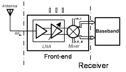
Radio-frequency front-end circuit with single-ended input differential output applied to ultra-wideband system
A single-ended input, differential output technology, applied in transmission systems, electrical components, improved amplifiers to reduce noise impact, etc., can solve problems such as unfavorable single-chip integration, LNA performance impact, poor performance, etc., to promote further integration, Effect with simple structure and variable gain
- Summary
- Abstract
- Description
- Claims
- Application Information
AI Technical Summary
Problems solved by technology
Method used
Image


Examples
Embodiment Construction
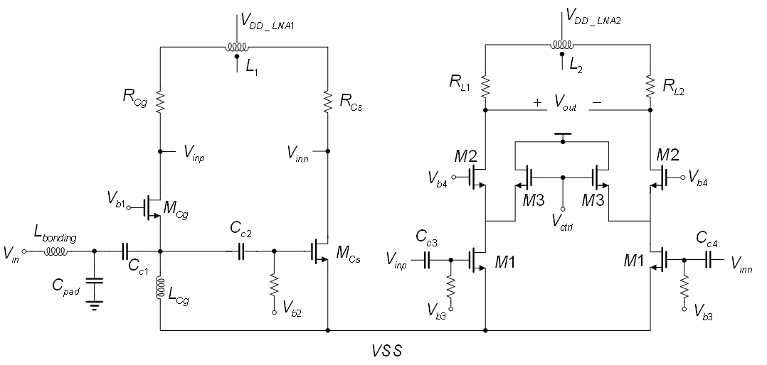
[0029] Further describe the present invention below in conjunction with accompanying drawing.
[0030] for figure 2 For the LNA shown, the input signal first passes through the series bonding inductor L bonding (The parasitic inductance introduced by the bonding line during the analog chip bonding is about 0.8nH) and the parallel pad capacitance C pad (The parasitic capacitance introduced by the PAD and ESD circuit of the analog chip is about 100fF) After the DC blocking capacitor C c1 Input point to common-gate branch and common-source branch. For the common gate branch, the input signal passes through the input inductor L cg Grounded, and connected to the input common gate tube M at the same time cgsource of M cg The drain end of the output is the positive end of the output, and at the same time it is connected to the load resistor R cg , R cg The other end of the load differential inductor L1 is connected to one end. For the common source branch, the input signal p...
PUM
 Abstract
Description
Claims
Application Information
 - R&D
- Intellectual Property
- Life Sciences
- Materials
- Tech Scout
- Unparalleled Data Quality
- Higher Quality Content
- 60% Fewer Hallucinations
Browse by: Latest US Patents, China's latest patents, Technical Efficacy Thesaurus, Application Domain, Technology Topic, Popular Technical Reports.
© 2025 PatSnap. All rights reserved.Legal|Privacy policy|Modern Slavery Act Transparency Statement|Sitemap|About US| Contact US: help@patsnap.com