Permanent magnet synchronous motor with high-power density
A permanent magnet synchronous motor, high power density technology, used in synchronous machines, synchronous machine parts, electromechanical devices, etc., can solve the problems of large motor volume and reduced motor efficiency, achieve high space utilization, improve cooling capacity, The effect of increasing power density
- Summary
- Abstract
- Description
- Claims
- Application Information
AI Technical Summary
Problems solved by technology
Method used
Image
Examples
specific Embodiment approach 1
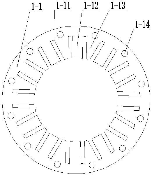
[0013] Specific embodiment one: the following combination figure 1 and Figure 4 This embodiment is described. This embodiment includes a stator and a rotor, and an air gap is formed between the stator and the rotor.
[0014] The stator includes armature core 1-1 and armature winding 1-2,
[0015] The air gap side surface of the armature iron core 1-1 is a toothed slot structure, and a plurality of parallel grooves 1-11 form the spaced arrangement of parallel teeth 1-12 and trapezoidal teeth 1-13 on the air gap side surface of the armature iron core 1-1 , the side of the air gap of the trapezoidal teeth 1-13 is the short side, and the middle of the root of each trapezoidal tooth 1-13 is provided with an axial circular through hole 1-14;
[0016] The armature winding 1-2 is sleeved on the parallel teeth 1-12, and the armature winding 1-2 is composed of centrally formed single-layer coils in series or in parallel, and the coils are square.
[0017] The motor described in thi...
specific Embodiment approach 2
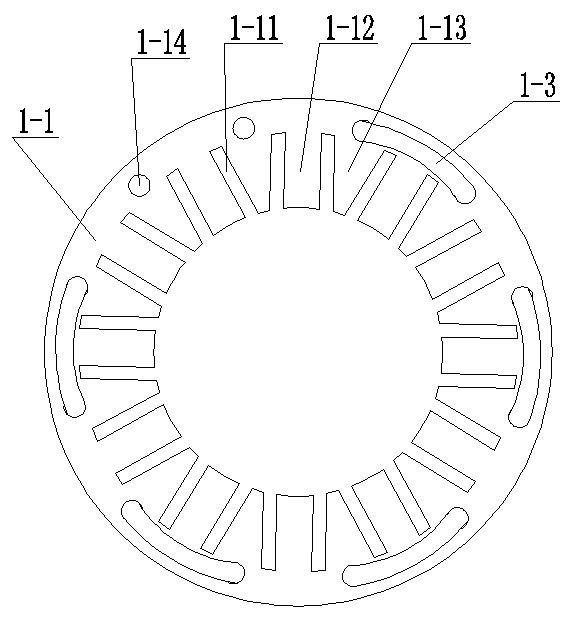
[0019] Specific embodiment two: the following combination figure 2 Illustrating this embodiment, the difference between this embodiment and the first embodiment is that the stator further includes cooling pipes 1-3, and each circular through hole 1-14 is embedded with a cooling pipe 1-3, and the phases along the circumferential direction Adjacent cooling pipes 1-3 are connected in series on both sides of the armature core 1-1 in a serpentine shape to form a cooling pipe. Other components and connection relationships are the same as those in the first embodiment.
[0020] Cooling liquid can be introduced into the cooling pipes formed by the series of cooling pipes 1-3 to cool the motor. This high-performance cooling method can greatly improve the cooling capacity of the motor, thereby effectively improving the power density of the motor.
specific Embodiment approach 3
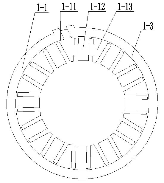
[0021] Specific embodiment three: the following combination image 3 Describing this embodiment, the difference between this embodiment and Embodiment 1 is that the stator further includes a cooling pipe 1-3 and a plurality of heat conduction heat pipes, and the two end faces of the armature core 1-1 are formed by circular through holes 1-14. A circular cooling pipe 1-3 is respectively fixed at the formed circumference;
[0022] Each circular through hole 1-14 is embedded with a heat-conducting heat pipe. The two ends of the heat-conducting heat pipe are two cold ends. One cold end is embedded in a cooling pipe 1-3, and the other cold end is embedded in the other. Inside the cooling pipes 1-3. Other components and connection relationships are the same as those in the first embodiment.
[0023] Cooling liquid is passed through the cooling pipes 1-3. The heat-conducting heat pipe is an internal vacuum structure, and the boiling point of the liquid inside is particularly low. ...
PUM
 Abstract
Description
Claims
Application Information
 - R&D
- Intellectual Property
- Life Sciences
- Materials
- Tech Scout
- Unparalleled Data Quality
- Higher Quality Content
- 60% Fewer Hallucinations
Browse by: Latest US Patents, China's latest patents, Technical Efficacy Thesaurus, Application Domain, Technology Topic, Popular Technical Reports.
© 2025 PatSnap. All rights reserved.Legal|Privacy policy|Modern Slavery Act Transparency Statement|Sitemap|About US| Contact US: help@patsnap.com


