
Test device and test method for limit heat-flow density of porous material for heat pipe

A heat flux density and testing device technology, applied in the field of heat pipe heat transfer, can solve the problems of working fluid pressure loss, small permeability, low permeability, etc., and achieve the effect of stable data and good data consistency

Active Publication Date: 2010-10-27
UNIV OF SCI & TECH BEIJING
View PDF5 Cites 11 Cited by
  • Summary
  • Abstract
  • Description
  • Claims
  • Application Information

AI Technical Summary

Problems solved by technology

However, the simple channel structure also has some disadvantages: due to the large capillary radius, the capillary pressure it generates is small; when the heat pipe is partially overheated and partially burnt out, the viscosity limit will suddenly appear, causing the temperature of the heat pipe to rise rapidly and the heat pipe to burn out;
[0008] However, due to the too small permeability, the working fluid will produce a large pressure loss when passing through the sintered capillary core;
[0009] 3. The capillary pressure of the wire mesh capillary core is in the middle, and the permeability is small, so the working fluid will have a large pressure loss, and its thermal resistance is also large, and the lower heat will reach the heat transfer limit
In addition to the three basic structures of the capillary core structure, there is also a composite capillary core structure composed of the above three basic structures (such as a combination of a channel structure and a sintered structure). Different structures have different heat transfer capabilities. The pores of the same structure The difference in heat transfer rate and pore size will also cause a great change in heat transfer capacity. On the other hand, the boiling heat transfer process of porous materials is very complicated, and it is still impossible to use theory to explain the boiling process of porous materials.

Method used


Image

  • Test device and test method for limit heat-flow density of porous material for heat pipe
  • Test device and test method for limit heat-flow density of porous material for heat pipe
  • Test device and test method for limit heat-flow density of porous material for heat pipe

Examples


Embodiment Construction

[0045] Hereinafter, the present invention will be further described in detail based on the embodiments.

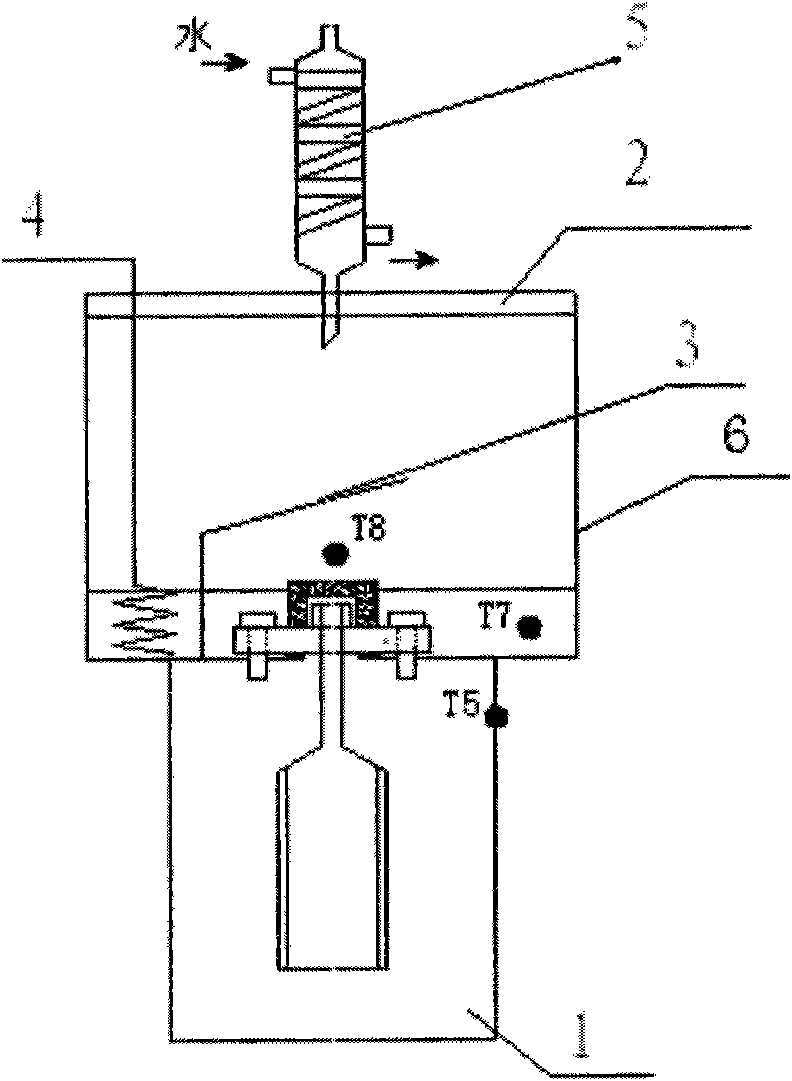
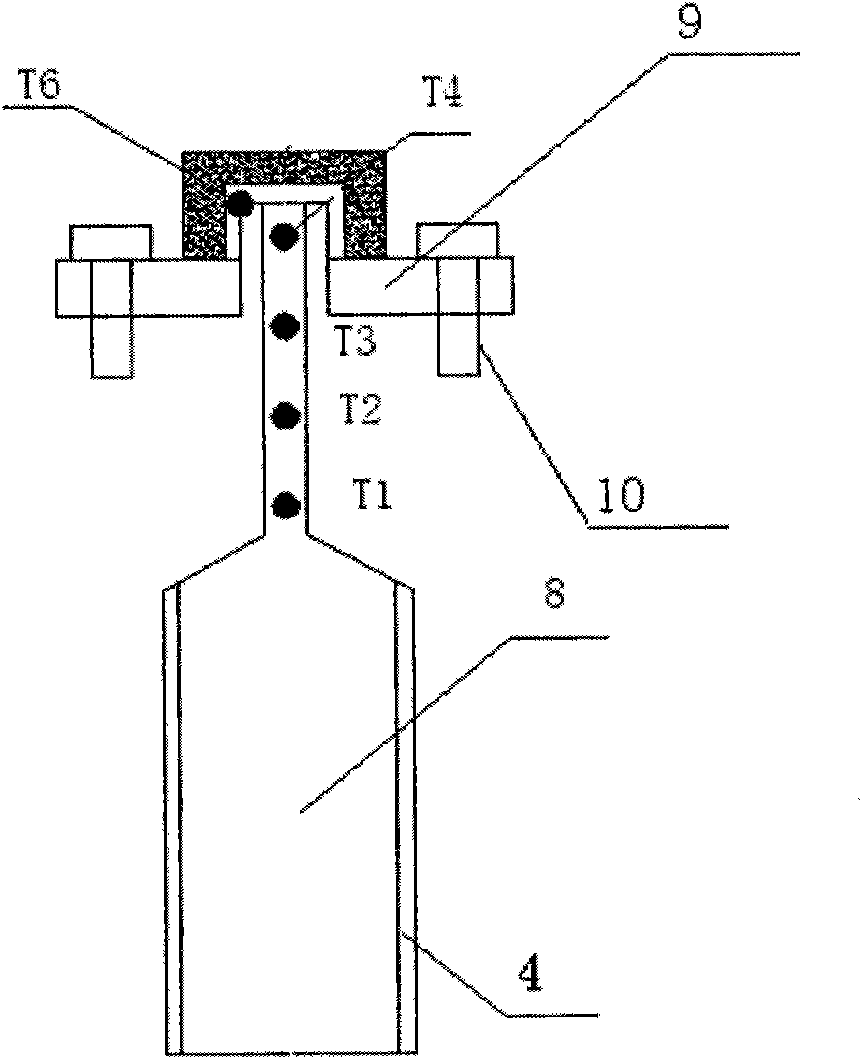
[0046] Such as figure 1 , figure 2 Shown is a testing device for the limit heat flux density of porous structural materials for heat pipes of the present invention. The device includes a thermal insulation material 1, a baffle 3, a heater 4, a condenser tube 5, a stainless steel barrel 6, a heat transfer block 7, and a thermocouple. 8 and test block 9;

[0047] The stainless steel barrel 6 is provided with a transparent heat-insulating glass cover 2, the condenser tube 5 enters the stainless steel barrel 6 through the through hole on the heat-insulating glass cover 2, the heater 4 and two thermocouples 9 (T7 and T8 respectively) are installed in stainless steel In the barrel 6, the test block 9 is fixed on the through hole at the bottom of the inner side of the stainless steel barrel 6 by screws 10. A thermocouple 9 (T6) is provided on the test block 9 and a baffle is provided...


PUM


Abstract

The invention relates to a test device and a test method for limit heat-flow density of a porous material for a heat pipe. The test device comprises a heat insulation material, a stainless steel barrel, a test block, a condensation pipe, a heat transfer block, a heater and thermocouples. The method comprises the following steps of: increasing the power of the heater so as to gradually increase the heat quantity of the porous material and intensify the boiling of the porous material till the occurrence of a heat transfer limit, and calculating the limit heat-flow density of the material through data recorded by each thermocouple. The device and the method have the advantages that: the heat resistance and the heat transfer capability of different capillary structures during boiling can be compared by the device and the method, the test results are stable and reliable, and the device and the method can provide help for the design of the capillary structures of heat pipes.

Description

Technical field [0001] The invention belongs to the technical field of heat transfer of heat pipes, and specifically relates to a testing device and a testing method for the limit heat flux density of a porous material for a heat pipe. Background technique [0002] With the development of electronic products in the direction of miniaturization, light weight and multi-function, the heat dissipation problem of electronic products has become more and more prominent. Traditional heat dissipation methods include metal heat sinks and air convection, but these methods have gradually been unable to meet the heat dissipation requirements of electronic products, and there is an urgent need for a stronger heat dissipation method. [0003] When the heat pipe is working, the working fluid in the pipe undergoes a phase change, and the latent heat of the phase change is transferred through the heat pipe. Generally, the thermal conductivity of a heat pipe is 100 to 10,000 times that of pure coppe...

Claims


Application Information

Patent Timeline
IPC IPC(8): G01N25/20
Inventor 曲选辉何东升何新波李平颜丞铭郭俊国胡伟华
Owner UNIV OF SCI & TECH BEIJING
Learn More