Eureka AIR delivers breakthrough ideas for toughest innovation challenges, trusted by R&D personnel around the world.

Method for reducing SO2 content in exhaust gas in production of sulfuric acid

A technology of SO2 and exhaust gas, applied in the field of sulfuric acid, can solve problems such as equipment corrosion, corrosion, and small market demand, and achieve low maintenance costs, increase sulfuric acid output, and significant environmental protection effects

Inactive Publication Date: 2010-10-20
WENGFU (GRP) CO LTD
View PDF5 Cites 18 Cited by
  • Summary
  • Abstract
  • Description
  • Claims
  • Application Information

AI Technical Summary

Problems solved by technology

Existing technology cannot achieve
[0003] At present, the commonly used sulfuric acid tail gas desulfurization method is the acid method, that is, the sulfuric acid tail gas is circularly washed with ammonia salt solution. This method mainly has the following disadvantages: ① This method is a wet desulfurization method, and the equipment is severely corroded, especially if the process control is slightly improper. Severe corrosion occurs, which affects the long-term stable operation of the device and increases maintenance costs; ②The overflow of ammonia is serious, that is, during the process of washing sulfuric acid tail gas with ammonia salt solution, ammonia will volatilize and overflow, which not only increases production costs, but also causes Secondary pollution; ③The by-product of desulfurization is ammonium sulfate, the market demand is not large, and sales are difficult

Method used


Image

  • Method for reducing SO2 content in exhaust gas in production of sulfuric acid

Examples


Embodiment

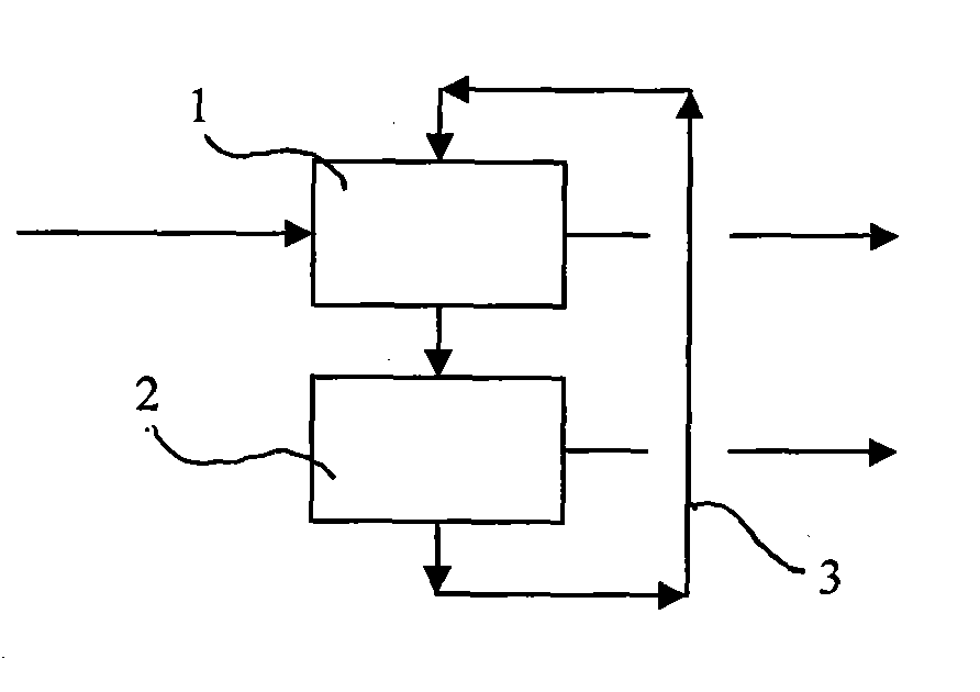
[0021] The sulfuric acid branch of Wengfu Phosphate Fertilizer Plant added a tail gas desulfurization device consisting of an adsorption tower and a desorption tower between the second acid absorption tower of the existing sulfuric acid plant and the tail gas discharge chimney, as a bypass line of the tail gas pipeline; the adsorption tower consists of two Cross-flow bed adsorption layer, a gas distribution chamber and two gas collection chambers, where each adsorption layer length × width × height = 13000mm × 1000mm × 15000mm, gas distribution chamber length × width × height = 13000mm × 2000mm × 15000mm, Length × width × height of each gas collection chamber = 13000mm × 1000mm × 15000mm; the desorption tower is a square vertical shell-and-tube heat exchanger, length × width × height = 49000mm × 2800mm × 12000mm, and the heat exchange tubes are arranged in a serpentine shape The steam heating tube and the heat exchange tube are φ19×3.8.

[0022] During production and operation...


PUM


Abstract

The invention relates to a method for reducing SO2 content in exhaust gas in production of sulfuric acid, which comprises the following steps that: an exhaust gas desulfurization device formed by an adsorption tower and a desorption tower is additionally arranged between a second acid absorber of the existing sulfuric acid device and an exhaust gas emission chimney; the sulfuric acid exhaust gas is guided into the adsorption tower, part of SO2 in the exhaust gas is adsorbed by an active coke desulfurization agent, and the exhaust gas from which part of SO2 is removed is adsorbed to be exhausted by the chimney; the adsorbed SO2 is chemically reacted with oxygen and water to produce sulfuric acid; the active coke desulfurization agent filled and flowed out of the adsorption tower enters the desorption tower and is heated, sulfuric acid or sulfate accumulated in active coke is decomposed and desorbed, and the desorbed high-concentration SO2 is sent back to the conversion section of the sulfuric acid device; and the desorbed active coke desulfurization agent enters the adsorption tower again to be circulated for reabsorbing. The method of the invention has high desulfurization efficiency, and the concentration of SO2 in exhaust gas in the production of the sulfuric acid is less than 120mg / m3, thereby greatly reducing the pollution of the SO2 on the atmosphere, and having obvious environmental effects; and the removed SO2 is directly sent back to the conversion section to be recovered, thereby increasing the yield of sulfuric acid.

Description

technical field [0001] The present invention relates to sulfuric acid, and further to the tail gas produced by sulfuric acid, specifically, to reducing SO in the tail gas by adsorption 2 content method. Background technique [0002] In traditional sulfuric acid production, SO 2 After two conversions and two absorptions, the tail gas is directly discharged into the atmosphere. In the past, the emission index required by the state was SO 2 ≤1200mg / m 3 , and the emission index of the newly built device is SO 2 ≤960mg / m 3 . With the national emission of SO 2 There are more and more stringent requirements for indicators and total emissions, and the sulfuric acid tail gas emission indicators must be reduced to 400mg / m 3 the following. Existing technology cannot reach. [0003] At present, the commonly used sulfuric acid tail gas desulfurization method is the acid method, that is, the sulfuric acid tail gas is circularly washed with ammonia salt solution. This method mainl...

Claims


Application Information

Patent Timeline
Patent Type & Authority Applications(China)
IPC IPC(8): B01D53/06
Inventor 岑祖望宋光辉
Owner WENGFU (GRP) CO LTD
Why Eureka
Eureka Blog
Learn More