
Reflecting surface of deployable antenna based on shape memory polymer and manufacturing method of skeleton structure thereof

A technology of memory polymer and skeleton structure, applied to antennas, antennas, electrical components and other directions suitable for movable objects, can solve the problems of large weight of deployable antennas, unstable deployment and contraction, complex structure, etc., and achieve convenience The expansion and contraction process, the smooth expansion movement process, and the effect of less system structure and control links

Active Publication Date: 2010-09-29
HARBIN INST OF TECH
View PDF3 Cites 13 Cited by
  • Summary
  • Abstract
  • Description
  • Claims
  • Application Information

AI Technical Summary

Problems solved by technology

[0005] In order to solve the problems of the existing deployable antennas used in spaceflight, such as heavy weight, large volume, complicated structure, and unstable deployment and contraction, the present invention proposes a deployable antenna reflective surface and its skeleton structure based on shape-memory polymers. method

Method used


Image

  • Reflecting surface of deployable antenna based on shape memory polymer and manufacturing method of skeleton structure thereof
  • Reflecting surface of deployable antenna based on shape memory polymer and manufacturing method of skeleton structure thereof
  • Reflecting surface of deployable antenna based on shape memory polymer and manufacturing method of skeleton structure thereof

Examples


specific Embodiment approach 1

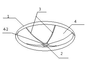
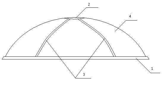
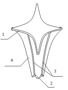
[0021] Specific implementation mode one: combine figure 1 , figure 2 Describe this embodiment, a deployable antenna reflective surface based on shape memory polymer, which is composed of a hoop power member 1, a hoop stiffener 2, a radial stiffener 3 and a reflective surface 4, the reflective surface 4 It is an annular paraboloid with a circular opening 4-2 at the bottom. The upper edge of the convex paraboloid of the reflective surface 4 is fixedly connected with a hoop power part 1, and the lower edge of the convex paraboloid of the reflective surface 4 is fixedly connected with a hoop. The reinforcement 2, the reflective surface 4 between the hoop power element 1 and the hoop reinforcement 2 is provided with radial reinforcements 3 arranged in the circumferential direction, the radial reinforcement is a parabolic strip, the The hoop power member 1 , the hoop reinforcement 2 , the radial reinforcement 3 and the reflective surface 4 are all made of shape memory polymer ma...

specific Embodiment approach 2

[0024] Specific implementation mode two: The difference between this embodiment and specific embodiment 1 is that the thickness of the hoop power part 1, the hoop reinforcement part 2 and the radial reinforcement part 3 is 0.02-40mm; the radius of the hoop power part 1 is: 0.5-60m; The radius of the hoop reinforcement 2 is 0.1-2m; the ratio of the focal length of the rotating paraboloid formed by the radial reinforcement 3 and the reflective surface 4 to the aperture of the hoop power element 1 is (0.025-2.5):1.

specific Embodiment approach 3

[0025] Specific implementation mode three: The difference between this embodiment and the first embodiment is that the heating method of the reflective surface 4 is electric heating, steam heating or outer space radiation heating when the reflective surface 4 is expanded, and the heating method of the reflective surface 4 is electric heating or steam heating when it shrinks.

[0026] The movement of the reflective surface 4 from the folded and contracted state to the unfolded state is realized by electric heating, steam heating or outer space radiation heating.


PUM

PropertyMeasurementUnit
Thicknessaaaaaaaaaa
Radiusaaaaaaaaaa
Radiusaaaaaaaaaa

Abstract

The invention provides a reflecting surface of a deployable antenna based on a shape memory polymer and a manufacturing method of a reflecting surface piece thereof, which relate to a reflecting surface of a deployable antenna and a manufacturing method of a reflecting surface piece. The invention solves the problems of large weight, large volume, complicated structure and unsteady deployment andcontraction of a traditional deployable antenna used for spaceflight. The deployable antenna is formed by splicing an annular power component, an annular reinforcement component, a radial reinforcement component and a reflecting film. The manufacturing method of the reflecting surface piece comprises the following steps of: (1) designing a mold; (2) preparing a shape memory polymer material; (3) coating a fibre reinforced material by using the shape memory polymer material; (4) forming an uncured fibre-reinforced shape memory polymer blank; (5) putting the closed mold into a heating box and heating; and (6) demolding to obtain a skeleton structure taking the fibre-reinforced shape memory polymer as the material. The invention can be used as the reflecting surface of the deployable antennain the field of the spaceflight.

Description

technical field [0001] The invention relates to a manufacturing method of a deployable antenna reflection surface and a skeleton structure. Background technique [0002] Under the existing aerospace technology, due to the space limitation of the aerospace vehicle, the aerospace antenna reflector must be folded before launching, and it must be automatically unfolded when working in orbit; due to the load limit, the aerospace antenna reflector must reduce its weight as much as possible ; In addition, the high reliability of the antenna reflector should also be guaranteed. With the rapid development of space technology, satellite communication, radio astronomy and radar technology. Therefore, the aerospace antenna reflector requires a small-volume, light-weight and high-performance deployable technology. [0003] In recent years, the rapid development of smart materials has provided a broad development space for deployable antenna reflectors. Among them, the shape memory pol...

Claims


Application Information

Patent Timeline
IPC IPC(8): H01Q15/16H01Q1/28
Inventor 冷劲松刘彦菊兰鑫阳鹏
Owner HARBIN INST OF TECH
Learn More