Keyboard structure

A keyboard and keycap technology, applied in the direction of electrical components, electric switches, user/computer interaction input/output, etc., can solve the problems of product quality and pass rate reduction, difficulty, poor smoothness, etc., to reduce the inconvenience of use and difficulty, improve the overall use function, improve the effect of quality and pass rate

Inactive Publication Date: 2010-09-29
CHICONY ELECTRONICS
View PDF0 Cites 9 Cited by
  • Summary
  • Abstract
  • Description
  • Claims
  • Application Information

AI Technical Summary

Problems solved by technology

[0002] The continuous research and development and innovation of computer equipment and related peripheral electronic devices have led to the emergence of more and more practical and functional electronic devices on the market today, and most of the input electronic devices need to be activated through buttons Input text, numbers or commands, such as mouse, keyboard or joystick for games, light guns and other related peripherals with output / input control interface, so the design of the keyboard is also developing rapidly with this trend , and change it according to different needs. For example, the keys used on the keyboards of early desktop computers and the keys specially used for notebook computers are quite different. The emphasis is on the optimal design of light, thin, short, and small, so the keys used cannot have the same design as the keys on the desktop computer keyboard, but must be designed according to the different characteristics and requirements specified by the notebook computer. be changed
[0003] Most of the general keyboards are mechanically pressed with a plurality of keys. The key structure mainly includes key caps, elastic parts, circuit films and circuit boards. The key caps are supported by elastic parts in the upper cover. The upper and lower elastic deformation displacements make the keycap and the electrical contacts on the circuit film correspondingly conduct, and then the input / output terminals on the circuit film are electrically connected to the circuit board to press the keycap. The key code is transmitted to the electronic device, so that the relative display or text, number and command input actions can be performed on the display. However, because most of the existing keycaps are integrally molded by plastic injection, this molding method has certain manufacturing constraints. If it is necessary to open an additional mold, the cost is high, and it may also cause insufficient injection and volume shrinkage and deformation caused by cooling and solidification, which will greatly reduce product quality and pass rate; in addition, because the volume of electronic products tends to be smaller than Miniaturization to reduce the occupied space, while the existing plastic injection keycaps are thicker and still have a certain size after assembly, which does not meet the design requirements for thinner products. However, if the overall thickness of the keycaps is reduced, in addition to It will increase manufacturing difficulties and relatively increase the product defect rate, and when the user presses it for a long time, it will cause problems such as deformation, damage and loss due to insufficient structural strength; moreover, when the user enters for fast typing When in action, due to the influence of the above-mentioned plastic material characteristics of the keycap itself, the surface touch and smoothness are poor, which is not conducive to fast input, and the overall visual texture of the keycap surface is relatively lacking. If it is applied to High-priced electronic devices with higher requirements for quality and refinement cannot effectively highlight the user's personal taste and vision

Method used


Image

  • Keyboard structure
  • Keyboard structure
  • Keyboard structure

Examples


Embodiment Construction

[0026] In order to achieve the above-mentioned purpose and effect, the technical means and structure adopted by the present invention, the features and functions of the preferred embodiments of the present invention will be described in detail as follows, so as to facilitate a complete understanding.

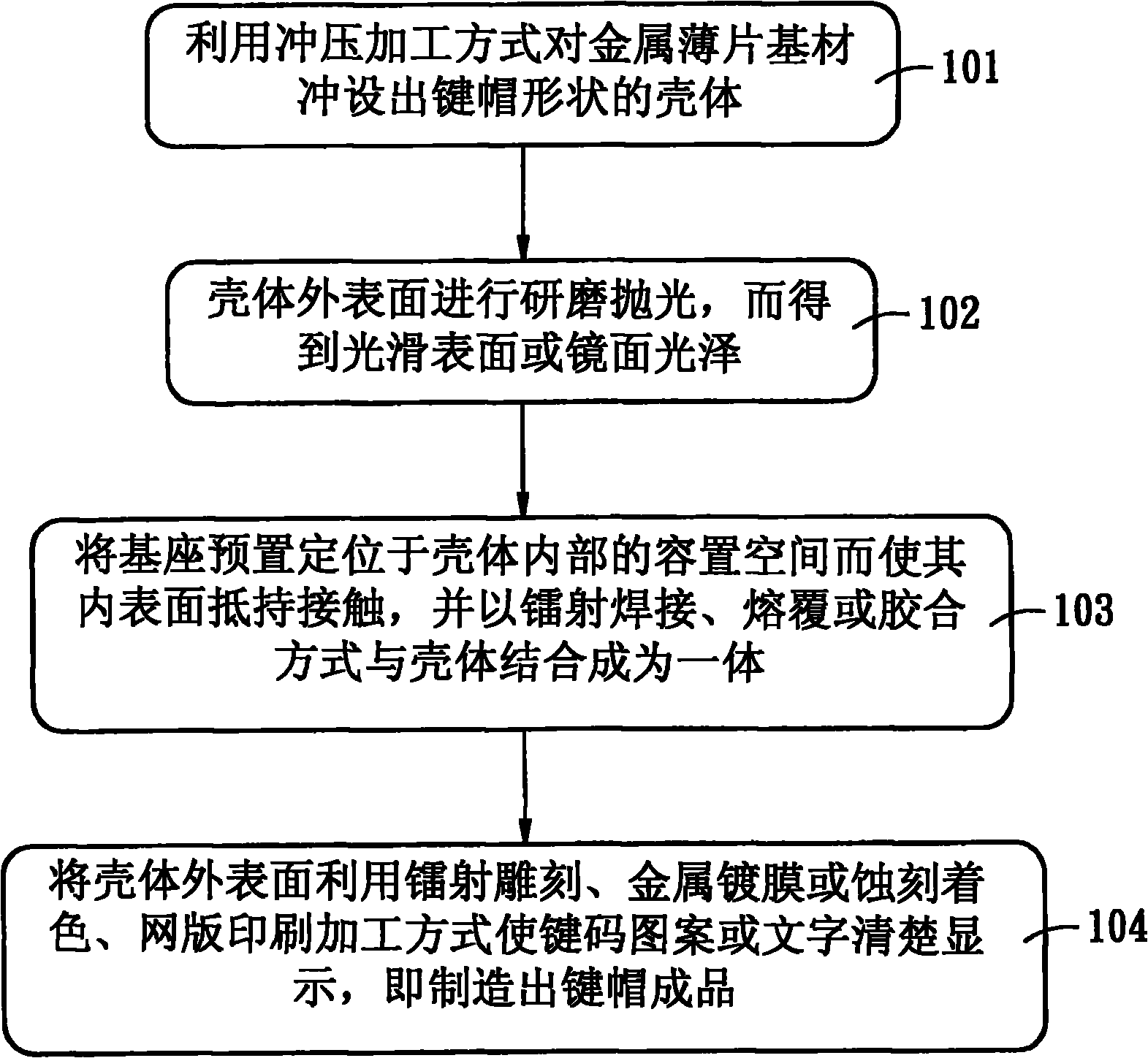
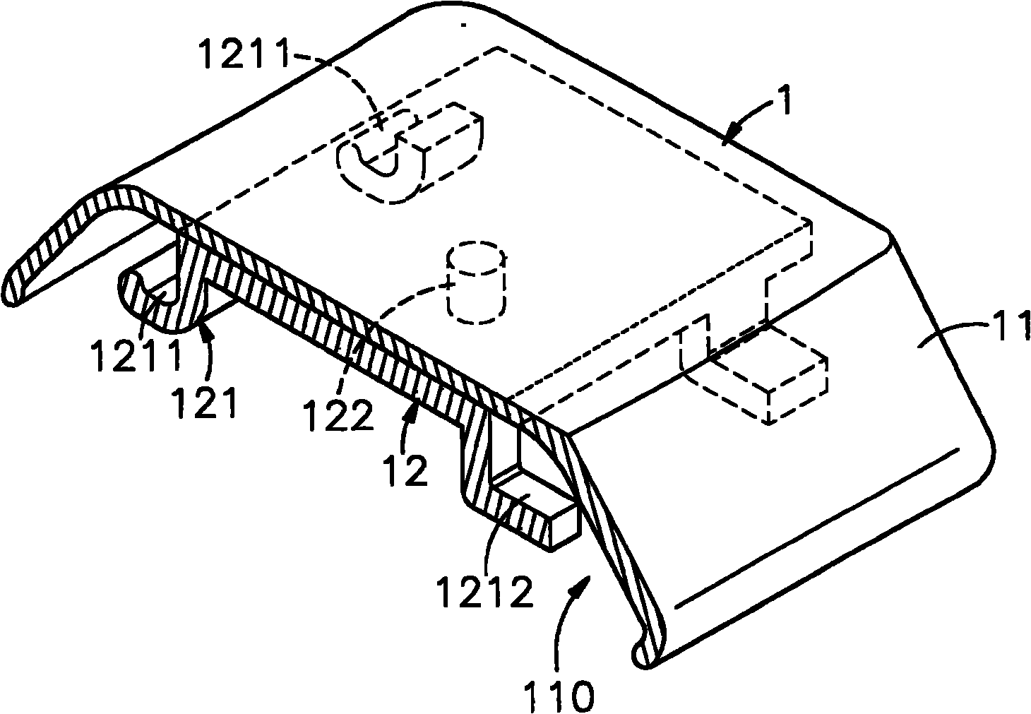
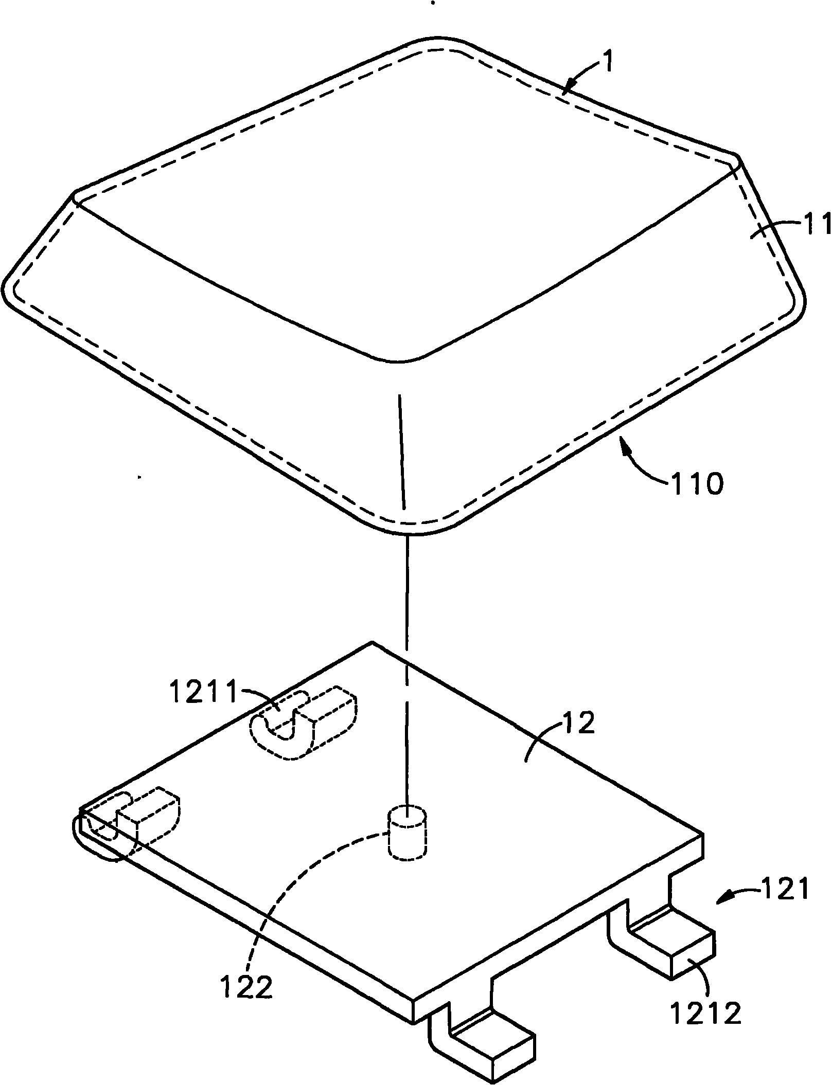
[0027] see figure 1 , figure 2 , image 3 Shown are respectively the manufacturing flow chart, structural diagram and three-dimensional exploded view of the present invention. It can be clearly seen from the figure that the manufacturing method of the keyboard of the present invention is processed according to the following process steps:

[0028] (101) punch out a keycap-shaped housing 11 on the sheet metal base material by means of a stamping process;

[0029] (102) Grinding and polishing the outer surface of the housing 11 to obtain a smooth surface or mirror luster;

[0030] (103) Pre-positioning the base 12 in the accommodating space 110 inside the housing 11 so that it...


PUM


Abstract

The invention discloses a keyboard structure, characterized in that a casing in the shape of a keycap is formed by stamping a metal foil base material in a manner of tool stamping and the external surface of the casing is ground and polished to result in smooth surface or specular gloss, a base having a jointing portion is stably and fixedly integrated with the inner surface of the casing in a manner of laser welding or gluing, and patterns or characters of key codes are formed on the external surface of the casing by means of laser graving, metal coating, etching coloration or screen printing, thus the keycap with such a thickness but certain thinness, excellent overall visual effect and great metallic texture and gloss is manufactured so that the surface of the keyboard structure is extremely outstanding in surface touch and pressing smoothness, and due to good structural strength, the keyboard structure is hardly deformed and damaged under pressing, thereby facilitating fast input of users and simultaneously reducing the using inconvenience and difficulty; the keyboard structure according to the invention includes better product competitiveness.

Description

technical field [0001] The invention relates to a keyboard structure, especially refers to punching a metal sheet into a keycap-shaped shell, and combining the base and the shell into one body to produce a metal-like keycap with a certain thickness, so that the touch and smoothness can be improved. And the structural strength is also better and it is not easy to produce deformation, which is convenient for users to input quickly and has more product competitiveness. Background technique [0002] The continuous research and development and innovation of computer equipment and related peripheral electronic devices have led to the emergence of more and more practical and functional electronic devices on the market today, and most of the input electronic devices need to be activated through buttons Input text, numbers or commands, such as mouse, keyboard or joystick for games, light guns and other related peripherals with output / input control interface, so the design of the keyb...

Claims


Application Information

Patent Timeline
Patent Type & Authority Applications(China)
IPC IPC(8): H01H13/70H01H13/705H01H13/86H01H13/88G06F3/02
Inventor 林志成
Owner CHICONY ELECTRONICS
Why Eureka
Try Eureka