
Power supply switching device and method thereof

A power switching and main power technology, applied in circuit devices, emergency power arrangements, electrical components, etc., can solve the problems of slow discharge of filter capacitors, circuit design that cannot meet low and high temperature working environments at the same time, slow switching speed, etc.

Inactive Publication Date: 2010-09-22
INVENTEC(NANJING) TECH CO LTD +2
View PDF2 Cites 24 Cited by
  • Summary
  • Abstract
  • Description
  • Claims
  • Application Information

AI Technical Summary

Problems solved by technology

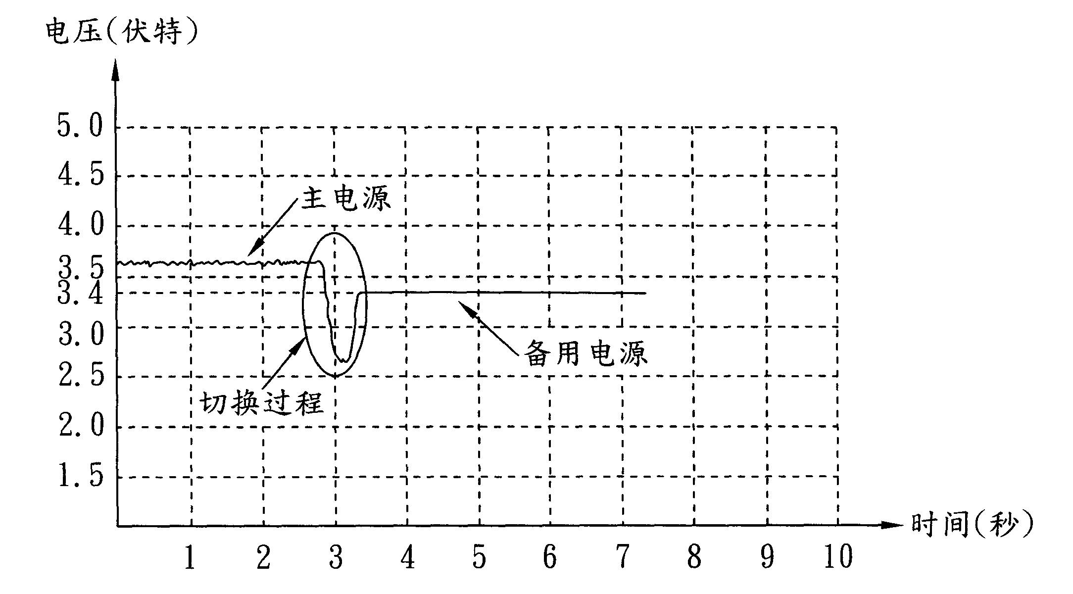
If a diode is used, the existing filter capacitor will discharge slowly, so the switching speed will be slowed down, and the vehicle supplier cannot be switched to the backup battery in time, resulting in the voltage drop phenomenon in the figure, resulting in intermittent power failure, which may easily cause GPS or The GPRS module is restarted, or the information lost in the use of GPS or GPRS module
If bipolar transistors are used to add voltage divider resistors, because bipolar transistors have temperature drift, and at the same time, the ratio of voltage divider resistors is relatively large, a large proportionality coefficient will amplify the influence of this temperature drift on circuit stability, and usually The operating temperature range required by the vehicle equipment is relatively wide, generally -40°C to 85°C, so the circuit design of this structure cannot meet the working environment of low temperature and high temperature at the same time, which will also cause the above problems

Method used


Image

  • Power supply switching device and method thereof
  • Power supply switching device and method thereof
  • Power supply switching device and method thereof

Examples


Embodiment Construction

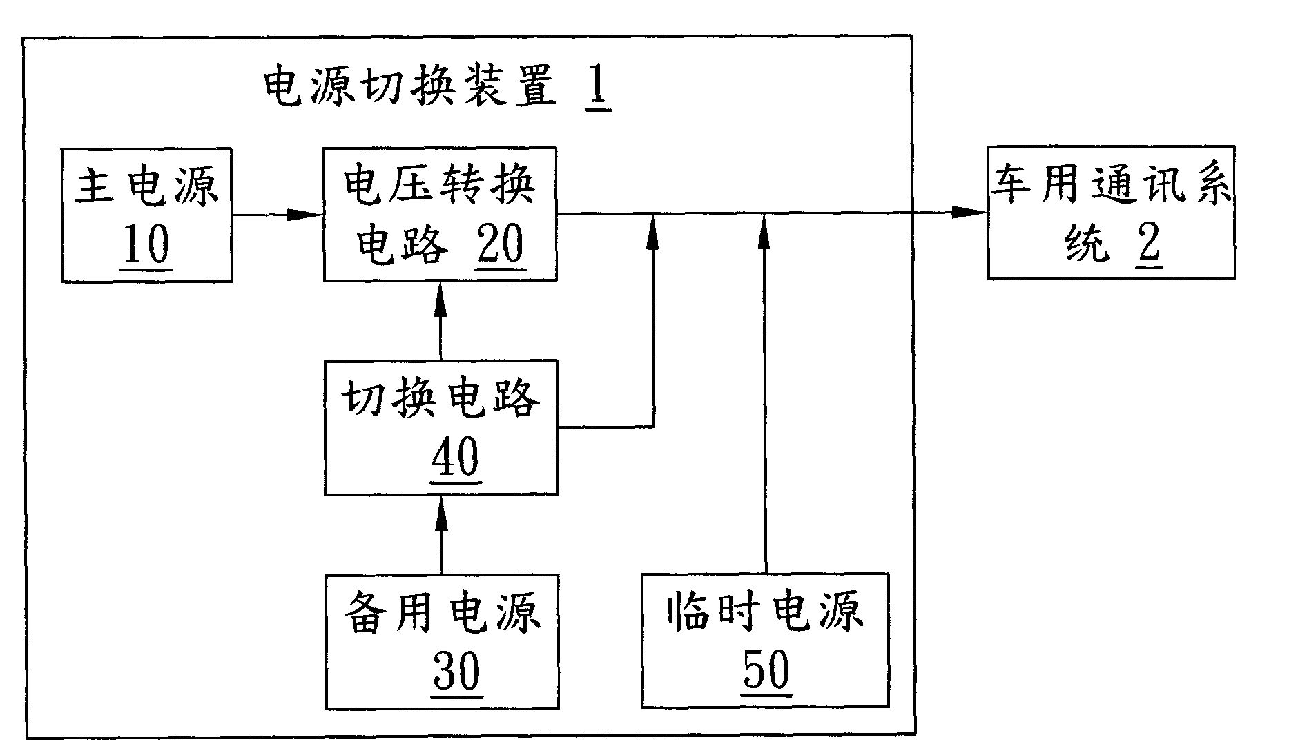
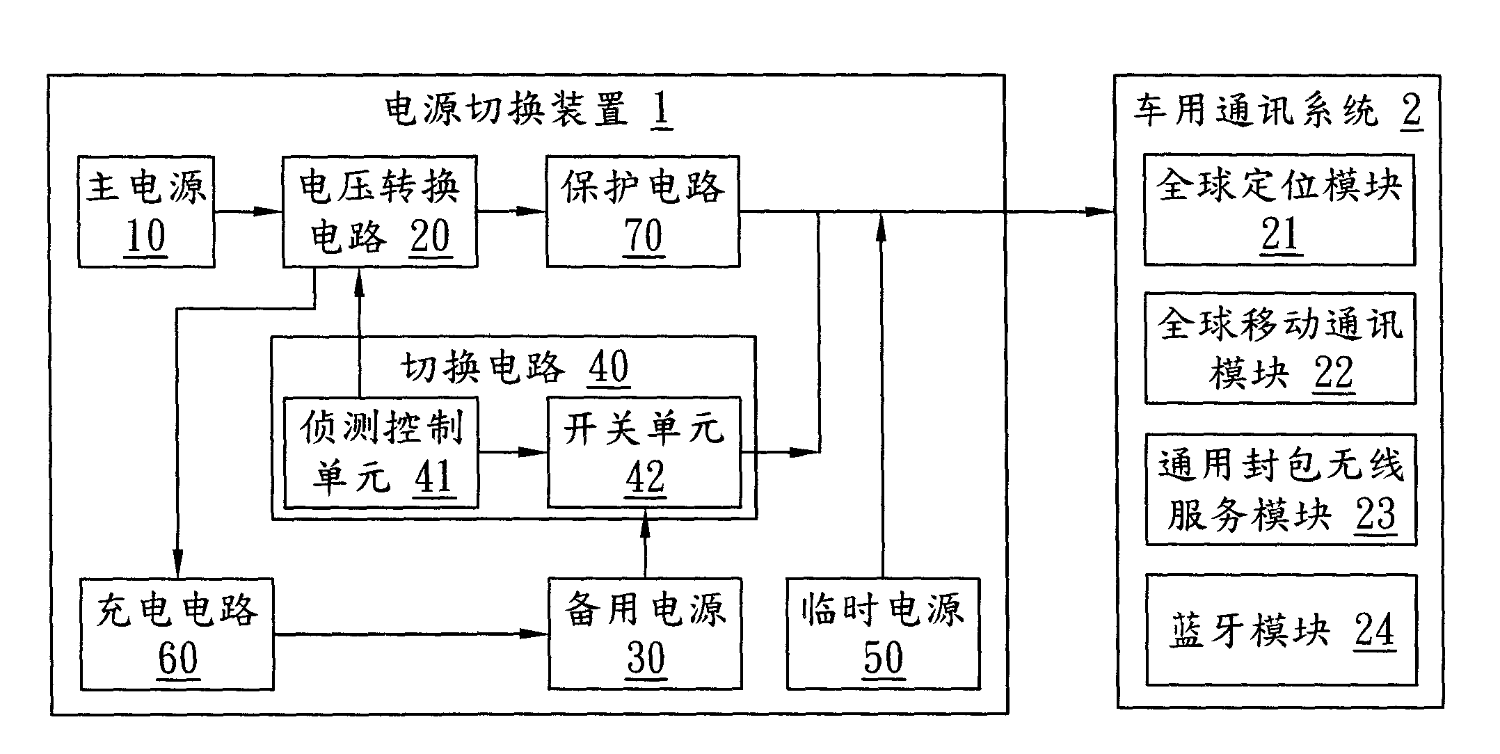
[0037] see figure 2 , which is a block diagram of the first embodiment of the power switching device of the present invention. In this figure, the power switching device 1 can be applied to a vehicle communication system 2, and the vehicle communication system 2 can include a global positioning (GPS) module 21, a global mobile communication (GSM) module 22, and a general packet radio service (GPRS) module 23 or Bluetooth (BT) module 24. The power switching device 1 includes a main power source 10 , a voltage converting circuit 20 , a backup power source 30 , a switching circuit 40 and a temporary power source 50 .

[0038] In the first implementation, the main power source 10 can be a vehicle battery to provide a first voltage, and the voltage value of the first voltage is usually 9 to 32 volts.

[0039] The voltage conversion circuit 20 is connected to the main power supply 10 to receive the first voltage and convert the first voltage into a second voltage to provide the s...


PUM


Abstract

The invention discloses a power supply switching device which is applied to a vehicle communication system. The power supply switching device comprises a main power supply, a voltage converting circuit, a backup power supply, a switching circuit and a temporary circuit, wherein the main power supply can provide a first voltage; the voltage converting circuit is connected with the main power supply for receiving the first voltage and converting the first voltage into a second voltage to the vehicle communication system; the switching circuit is connected with the voltage converting circuit, the backup power supply and the vehicle communication system and detects the first voltage value of the first voltage or a second voltage value of the second voltage; when the first voltage value or the second voltage value is smaller than a threshold value, the switching circuit switches the main power supply to the backup power supply for supplying power to the vehicle communication system; and a temporary power supply is connected with the voltage converting circuit, the switching circuit and the vehicle communication system for providing power supply needed by a vehicle communication device in the switching process.

Description

technical field [0001] The present invention relates to a power switching device and its method, in particular to a power switching device capable of generating a smooth voltage curve during the power switching process and its method. Background technique [0002] In addition to the vehicle power supply, the current communication systems used in vehicles also have a backup battery. When the vehicle power supply is powered off, the backup battery will continue to supply power to maintain the normal communication system. Electricity required for work. [0003] This communication system usually includes a global positioning module (GPS), Bluetooth (BT) or general packet radio service (GPRS) module. When using these modules, it needs to maintain high power at certain times to provide instantaneous high current. Input to the car communication system. [0004] see figure 1 , which is a schematic diagram of voltages switched between different power sources of a conventional powe...

Claims


Application Information

Patent Timeline
IPC IPC(8): H02J9/06
CPCY02B70/30Y04S20/20
Inventor 刘永康邹峥嵘
Owner INVENTEC(NANJING) TECH CO LTD
Learn More