Spinning head

A spinneret, filament technology, applied in spinneret assembly, filament forming process, textile and papermaking, etc., can solve the problem of melt inlet overlapping melt inlet sealing and so on

Inactive Publication Date: 2010-09-22
OERLIKON TEXTILE GMBH & CO KG
View PDF9 Cites 14 Cited by
  • Summary
  • Abstract
  • Description
  • Claims
  • Application Information

AI Technical Summary

Problems solved by technology

However, in spinnerets where the two eccentrically located melt inlets have to be bridged relative to the nozzle seat along the separation plane during installation and dismounting, this relative movement creates a tendency for the melt inlets to overlap. problems and the sealing of the two melt inlets

Method used


Image

  • Spinning head
  • Spinning head
  • Spinning head

Examples


Embodiment Construction

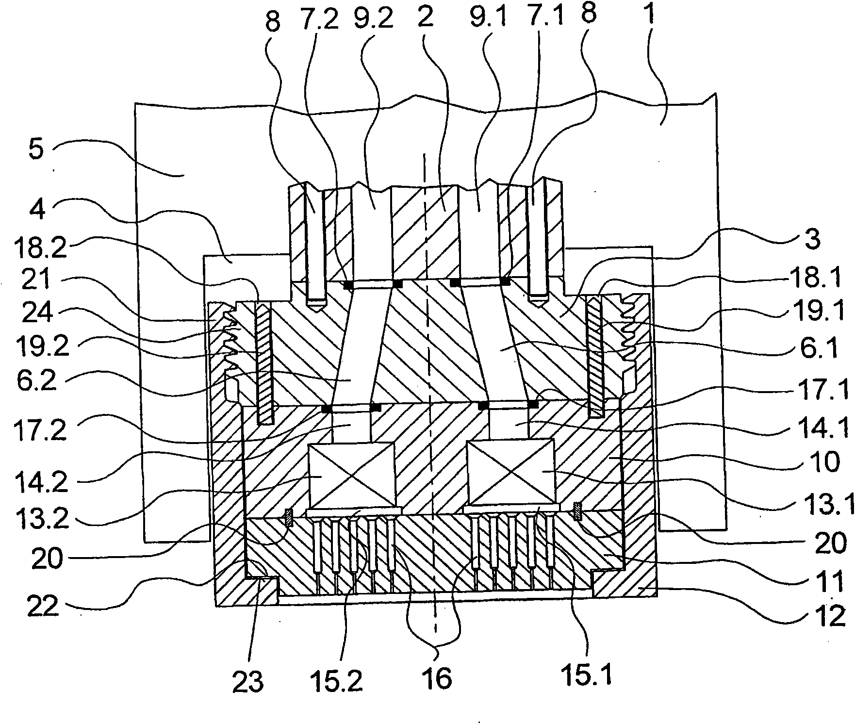
[0025] figure 1 A first exemplary embodiment of the spinneret according to the invention is illustrated by way of example in a cross-sectional view. The exemplary embodiment comprises a nozzle holder 1 which has a nozzle receptacle 4 on its bottom side which extends between heating jackets 5 . In the central region of the nozzle receptacle 4 there is an adapter plate 2 which is fixedly connected to the nozzle holder 1 . The adapter plate 2 has two melt connections 9.1 and 9.2, which are in any case connected in the usual manner to a spinning pump (not shown here) via distribution lines .

[0026] Arranged below the adapter plate 2 is an inlet plate 3 , which is connected to the adapter plate 2 in a rotationally fixed manner via a plurality of fastening devices 8 . The inlet plate 3 has melt feed channels 6 . 1 and 6 . 2 , which are adjacent to one another and are assigned to melt connections 9 . 1 and 9 . 2 in the adapter plate 2 . The parting surfaces between the melt con...


PUM


Abstract

The head has a round nozzle plate with a set of nozzle holes, a filter plate receiving filter elements, and an inlet plate with melt inlet channels. The three plates form a melt transport system within a housing. The housing is detachably connected to a nozzle support for introducing polymer melt. The inlet plate includes an external thread on a periphery, and is twist-resistantly held at the support. The housing includes an internal thread at a plug-in end. The housing is connected with the external thread via the internal thread.

Description

technical field [0001] The invention relates to a spinneret for the melt spinning of a plurality of filaments according to the preamble of claim 1 . Background technique [0002] A spinneret is an integral part of a melt spinning unit for the continuous production of synthetic threads. The spinneret makes it possible to extrude a polymer melt into a plurality of thread-like filaments which are combined in several strands to form a synthetic thread. Spinnerets of this type therefore usually have a nozzle plate on their bottom side which contains a plurality of nozzle holes, through which the polymer melt is extruded to extrude filaments. The filaments are then combined into multifilament threads in a thread processing unit after the spinneret, coagulated and reprocessed, and finally wound into bobbins. In this case, the perfectly normal situation is that each spinneret produces one or more strands. Therefore, the recent trend is to use in particular multiple spinnerets so ...

Claims


Application Information

Patent Timeline
Patent Type & Authority Applications(China)
IPC IPC(8): D01D4/00D01D4/02D01D4/06D01D4/08D01D1/10
CPCD01D4/06D01D4/08
Inventor S·贝克尔A·迈D·科尔纳
Owner OERLIKON TEXTILE GMBH & CO KG
Why Eureka
Try Eureka