


Quick Research
Generate reliable direction feasibility study reports for your R&D in just a few steps.

Technical Q&A
Discover and master advanced knowledge NOW. Basics, ideas, possibilities, all at once.

Find Solutions
As an expert in R&D theories, this can generate solutions to your technical problems instantly.

Evaluate Feasibility
Analyze your overall solution with one click, know your potential R&D risks in advance.

Monitor Landscape
Get weekly tech updates, stay abreast of the latest tech innovations and key insights.
Seawater desalinator
A water-receiving tray, hollow technology, applied in seawater treatment, general water supply saving, infiltration/dialysis water/sewage treatment, etc., can solve the problems of high energy consumption and low efficiency
- Summary
- Abstract
- Description
- Claims
- Application Information
AI Technical Summary
Problems solved by technology
Method used
Image

Examples
specific Embodiment approach 1
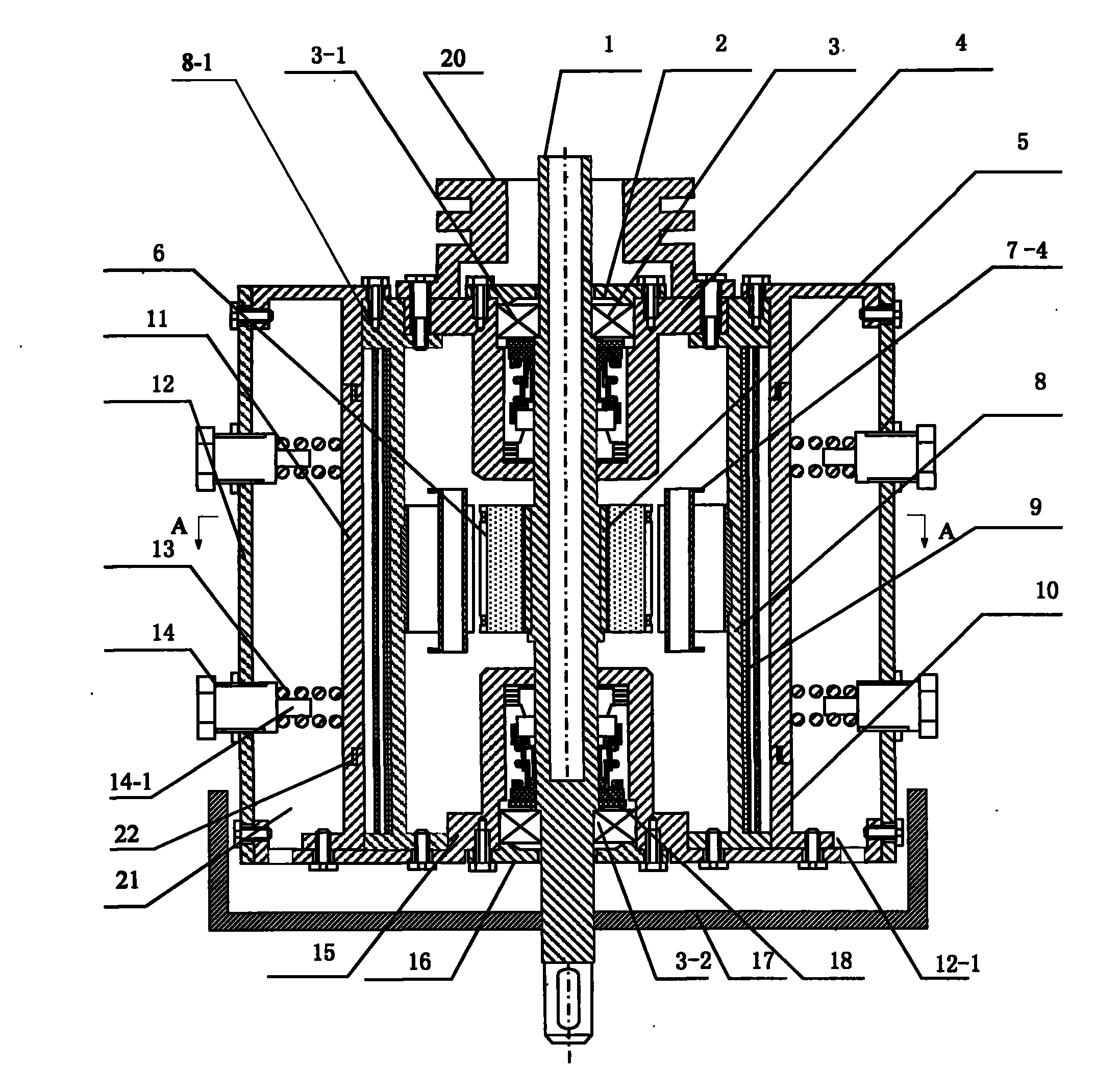
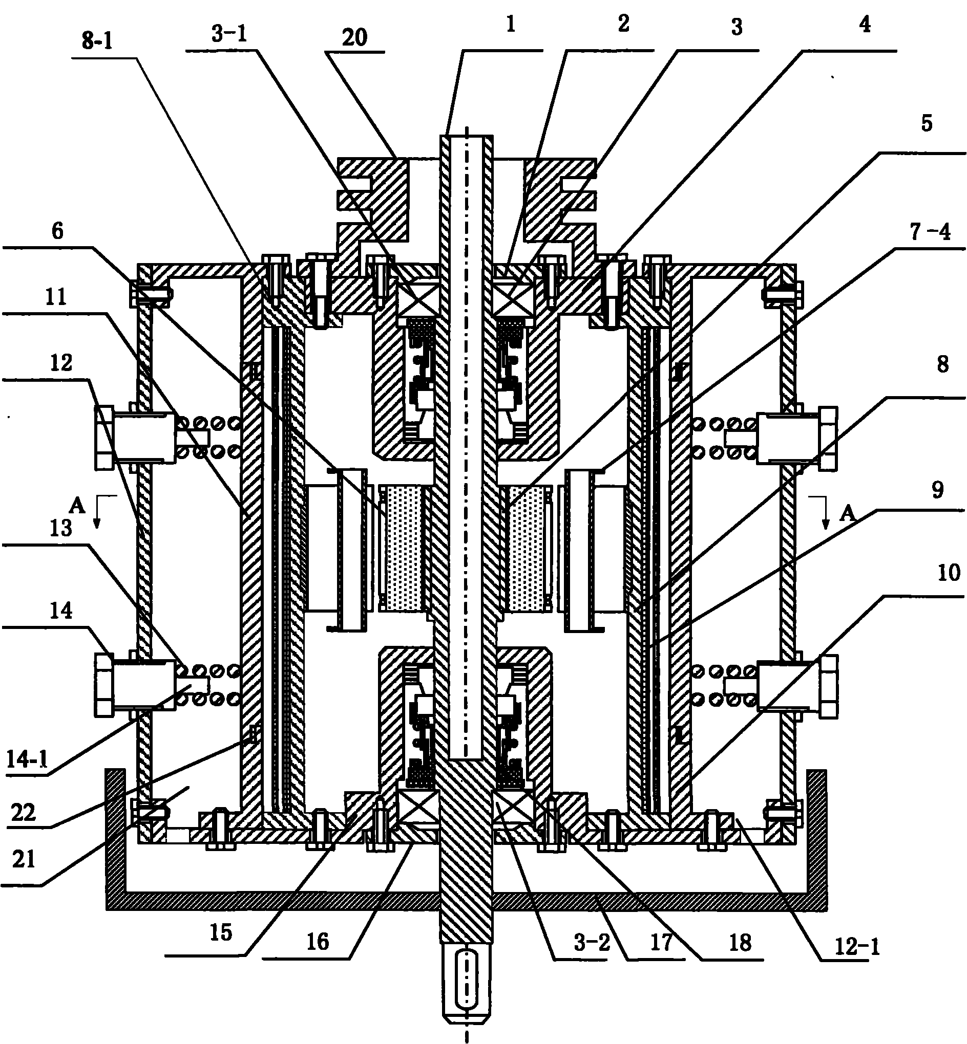
[0012] Specific implementation mode one: the following combination figure 1 and figure 2 This embodiment will be specifically described. This embodiment consists of a hollow shaft 1, an upper bearing cover 2, an upper end bearing 3-1, a lower end bearing 3-2, an upper end cover 4, a stator part, a rotor part, a lower end cover 15, a lower bearing cover 16, a water receiving tray 17 and two The hollow shaft 1 is a shaft whose upper end communicates with the inner chamber and whose lower end is closed;
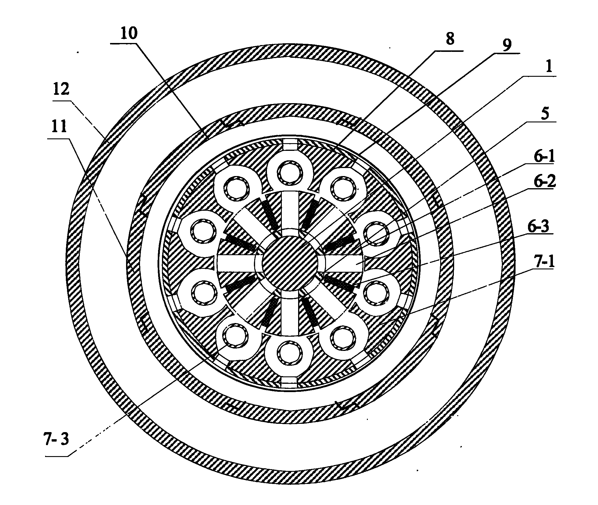
[0013] The stator component is composed of a stator core 6-1, several permanent magnets 6-3, and a magnetic isolation sleeve 5. On the stator core 6-1, a number of permanent magnets 6-3 tangentially magnetized along the stator core 6-1 are distributed along the circumferential direction Thus, N and S magnetic poles are alternately distributed on the surface of the stator core 6-1; the stator part is fixed at the middle position on the length of the hollow shaft 1, and the sta...
specific Embodiment approach 2
[0018] Specific implementation mode two: the following combination figure 1 This embodiment will be specifically described. The difference between this embodiment and the first embodiment is that a pulley 20 is fixed on the top end of the hollow shaft 1 .
[0019] When the external power (electric energy, wind energy or other mechanical energy, etc.) drives the rotor part to rotate through the pulley 20, a rotating magnetic field is formed, and the rotating magnetic field interlinks with the stator part through the air gap, except for hysteresis eddy current loss in the stator core 7-1 In addition, the resistance loss of the secondary short-circuit current generated by the induced potential in the cage-shaped conductive loop, the surface loss and pulsating loss generated by the air-gap permeance harmonic magnetic field caused by the slotting of the stator and rotor on the surface of the opposite iron core and the generation of rotor current All losses caused by the leakage ma...
specific Embodiment approach 3
[0022] Specific implementation mode three: the following combination figure 1This embodiment will be specifically described. The difference between this embodiment and Embodiment 1 is that the valve assembly also includes an extension rod 14-1, one end of the extension rod 14-1 is docked on the end of the adjustment screw 14, and the spring 13 is sleeved on the extension rod 14-1. 1 on the outer circular surface. With such setting, the work is more stable and reliable.
PUM
 Abstract
Description
Claims
Application Information
 - R&D Engineer
- R&D Manager
- IP Professional
- Industry Leading Data Capabilities
- Powerful AI technology
- Patent DNA Extraction
Browse by: Latest US Patents, China's latest patents, Technical Efficacy Thesaurus, Application Domain, Technology Topic, Popular Technical Reports.
© 2024 PatSnap. All rights reserved.Legal|Privacy policy|Modern Slavery Act Transparency Statement|Sitemap|About US| Contact US: help@patsnap.com