Solid combination switch device

A compound switch and solid-state technology, applied in reactive power compensation, reactive power adjustment/elimination/compensation, etc., can solve problems such as arcing, poor real-time performance of reactive power compensation, thyristor breakdown and burning, etc., to reduce the number of switching times, The overall structure is simple and the effect of increasing the service life

Active Publication Date: 2010-08-04
CHINA EPRI SCIENCE & TECHNOLOGY CO LTD +2
View PDF1 Cites 8 Cited by
  • Summary
  • Abstract
  • Description
  • Claims
  • Application Information

AI Technical Summary

Problems solved by technology

There are two problems in this method: one is manual splitting and paralleling of capacitor banks, requiring substation personnel on duty to pay attention to the reactive power of the system at all times, once the reactive power needs to be compensated, manually splitting and closing the circuit breaker to control the input and removal of parallel capacitor banks for compensation The reactive power of the system is poor in real time; secondly, because the reactive power of the system changes at any time, it is necessary to switch on and off the circuit breaker frequently, and there is a problem when the circuit breaker is cut off at a non-zero point of current and input at a non-zero point of voltage. arcing, which has a great impact on the service life of the circuit breaker
[0005] 1. It is impossible to calculate the reactive power of the system by itself, and automatically switch the power capacitor bank, which leads to poor real-time performance of reactive power compensation;
[0006] 2. The relay has poor breaking current capability, which limits this intelligent composite switch to be used only in low-voltage power distribution systems;
[0007] 3. There is no monitoring of the working state of the thyristor before triggering the thyristor. If the thyristor is damaged, the composite switch is always in a short circuit state, there is no fault alarm, and the composite switch cannot be taken out of operation.
[0008] 4. When the system voltage is high and multiple thyristors need to be connected in series, the control circuit in the patent cannot guarantee that the thyristors will be triggered at the same time, and it is easy to cause the thyristors to trigger out of sync and be burned by high voltage breakdown
[0009] Therefore, in view of many imperfect problems of the current manual switching power capacitor bank and the existing compound switch, the present invention provides a solid-state compound switch device to solve the above problems

Method used


Image

  • Solid combination switch device
  • Solid combination switch device
  • Solid combination switch device

Examples


Embodiment Construction

[0022] Next, the solid-state composite switch device of the present invention will be further described in conjunction with the accompanying drawings.

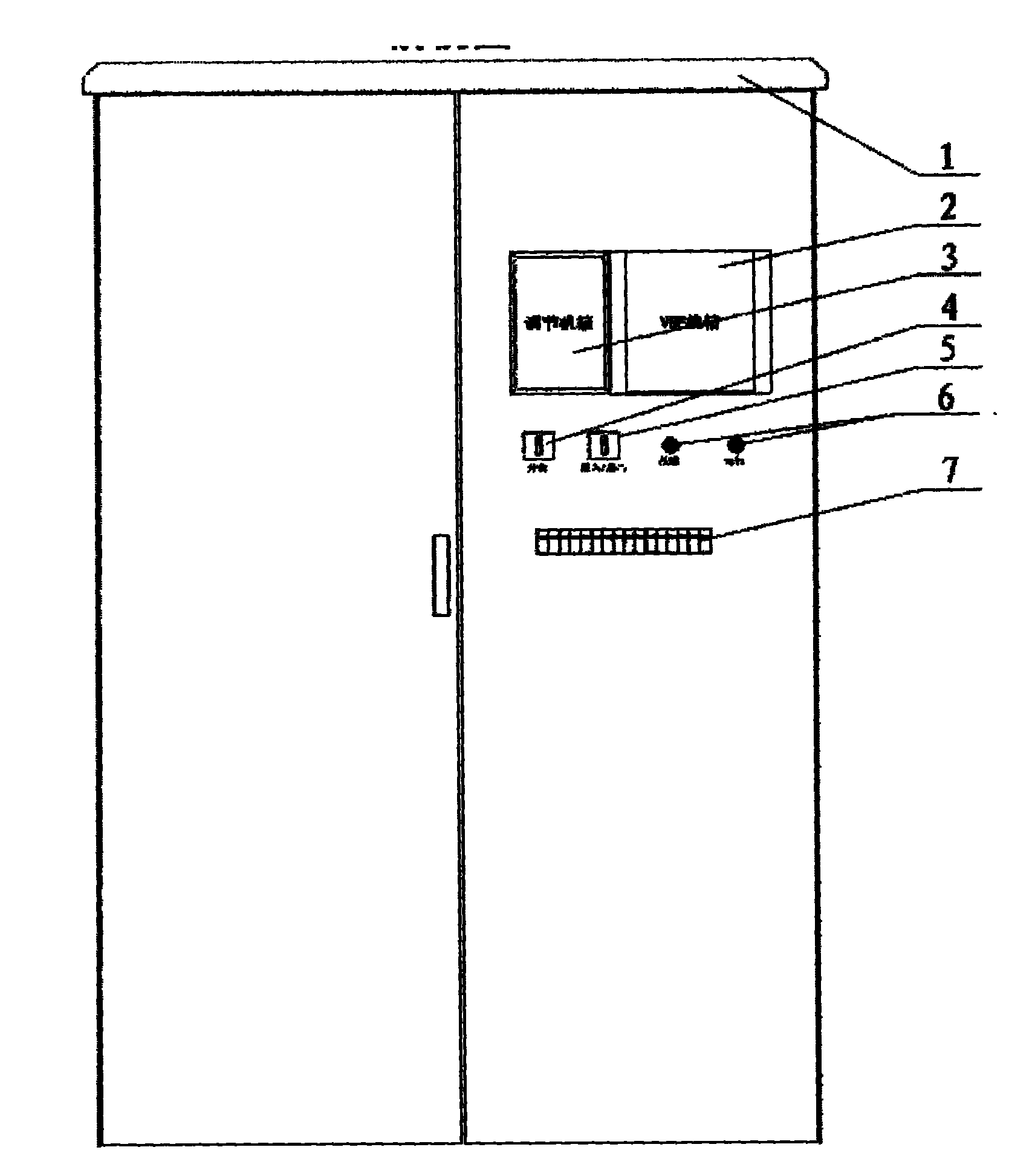
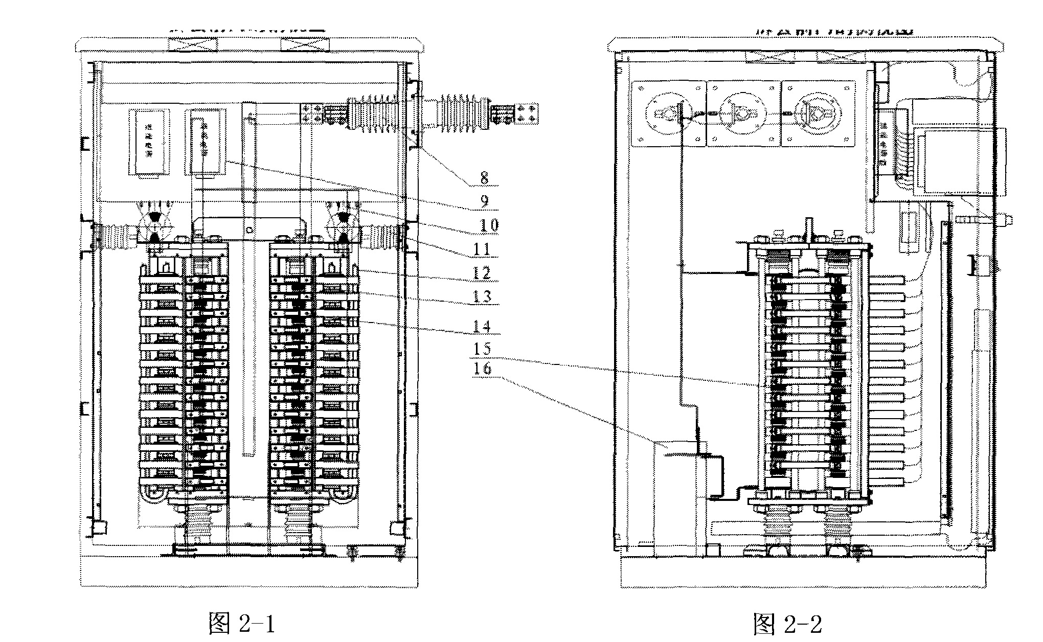
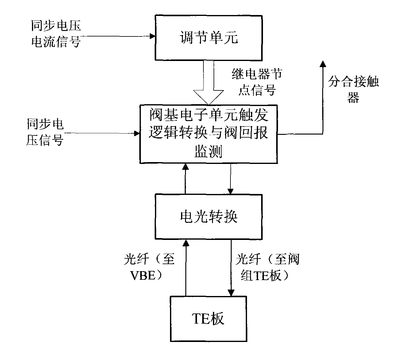
[0023] The solid-state composite switchgear of the present invention is installed in a power distribution cabinet as a whole, including a two-phase thyristor valve string, a three-phase contactor, a thyristor trigger board, a thyristor trigger board energy-sending inverter power supply, a high-frequency converter, and a step-up transformer , adjustment unit, valve base electronic unit, trigger and return optical fiber, working status wrench, contactor opening and closing wrench, AC and DC air switch, contactor opening and closing indicator light.

[0024] According to different voltage levels, the solid-state composite switchgear is divided into a high-voltage primary system part and a low-voltage secondary system part. Primary system solution: In a cuboid distribution cabinet, the three-phase voltage is connected to the bus b...


PUM


Abstract

The invention provides a solid combination switch device which can switch a parallel capacitor to a system automatically; the device is mainly used for reactive compensation of a high-voltage electric power system, zero passage (arcless) conduction and cut-off of a high-voltage electric power capacitor set is carried out automatically by calculating the reactive power value of the system; the solid combination switch device mainly comprises that: a thyristor, a contactor, a thyristor energy delivery system and a control system are integrated into a combined mechanism in an equipment cabinet, and an external connecting wire only needs three-phase voltage, electric current signals and direct-current 220V control power supply to realize the combination switch which can automatically switch the parallel capacitor set.

Description

technical field [0001] The invention belongs to the field of power system devices, and specifically relates to a control device that automatically calculates the real-time reactive value of the power system, triggers thyristors in phases and automatically switches contactors under the condition of ensuring no arc, so as to control the access of capacitor banks and cut-off solid-state composite switchgear. Background technique [0002] The solid-state composite switchgear is an intelligent switchgear installed in the power distribution cabinet, which automatically switches the power capacitor bank by calculating the reactive power of the power system at all times. The composite switch adopts the mode of parallel operation of thyristor and contactor. When switching on, the thyristor is first triggered, and then the contactor is switched on after a short time delay to realize the input at the zero-crossing point of the system voltage; when cutting off, the thyristor is first t...

Claims


Application Information

Patent Timeline
Patent Type & Authority Applications(China)
IPC IPC(8): H02J3/18
CPCY02E40/30
Inventor 李鹏李卫国马海超刘宏李志友赵刚
Owner CHINA EPRI SCIENCE & TECHNOLOGY CO LTD
Why Eureka
Try Eureka