
Method for improving brightness of LED chip

A technology of LED chips and brightness, which is applied in the direction of electrical components, circuits, semiconductor devices, etc., can solve the problems of large difference in refractive index and inability to export chips, etc., and achieve the effect of improving light extraction efficiency, brightness, and increasing the probability of escape

Active Publication Date: 2010-06-16
EPILIGHT TECH
View PDF0 Cites 16 Cited by
  • Summary
  • Abstract
  • Description
  • Claims
  • Application Information

AI Technical Summary

Problems solved by technology

At present, the light extraction efficiency of the chip is the main factor limiting the external quantum efficiency of the device. The main reason is that the refractive index difference between the substrate material, the epitaxial material, and the air is relatively large, which causes the light generated in the active region to completely occur at the interface of different refractive index materials. reflective and cannot export the chip

Method used


Image

  • Method for improving brightness of LED chip
  • Method for improving brightness of LED chip
  • Method for improving brightness of LED chip

Examples


Embodiment Construction

[0022] Take the 10*23mil chip as an example below to specifically illustrate the implementation process of the method of the present invention:

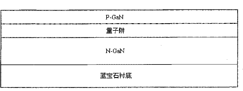
[0023] Step 1, utilize metal-organic chemical vapor deposition technique to grow GaN (gallium nitride) semiconductor layer on sapphire substrate, this layer comprises N-GaN layer, quantum well and P-GaN layer, as Figure 1A shown.

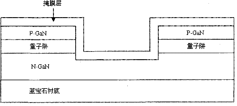
[0024] Step 2, using ICP Etching (Inductively Coupled Plasma Etching) or RIE (Reactive Ion Etching) technology to expose part of the N-GaN layer, and the etching depth is ,Such as Figure 1B Shown; In a specific embodiment, the etching depth is .

[0025] Step 3, vapor-depositing a metal layer Ni / Ag on the GaN semiconductor layer with a thickness of , the plating rates are , , using this metal layer as a mask layer, such as Figure 1C shown.

[0026] The metal layer is divided into two layers, the adhesion layer is in contact with the GaN layer, and the protection layer is in contact with the...


PUM

PropertyMeasurementUnit
Widthaaaaaaaaaa
Depthaaaaaaaaaa

Abstract

The invention discloses a method for improving brightness of an LED chip. The method comprises the following steps of: utilizing the metallic organic chemical vapor phase deposition to grow a GaN semiconductor layer comprising an N-GaN layer, a quantum well and a P-GaN layer on a sapphire substrate; utilizing the ICP Etching or RIE to make partial N-GaN layer exposed; coating a metallic layer on the GaN semiconductor layer by vaporization and using the metallic layer as a mask film layer; adopting the laser scribing technique to scribe the formed chip unit down to the sapphire substrate; corroding the N-GaN layer on the side wall of a scribing way by using the metallic layer as the mask film, so that the N-GaN layer forms a structure of a gradually changed inverted triangle; removing the metallic layer; manufacturing a transparent electrode, an N / P electrode and an SiO2 passivation layer on the corroded chip unit; and grinding the back of the LED wafer for thinning, and breaking the LED wafer by a breaking machine to obtain the LED chip. The method has the advantages of changing transmission distance of light, increasing a probability of photons escaping from the chip, improving the light outputting efficiency of the LED chip and making the brightness of the LED chip improved by over 10 percent.

Description

technical field [0001] The invention relates to the field of semiconductor light-emitting diodes, in particular to a method for improving the brightness of LED chips. Background technique [0002] Light-emitting diodes have the advantages of small size, high efficiency and long life, and are widely used in traffic indication, outdoor full-color display and other fields. In particular, the use of high-power light-emitting diodes may realize semiconductor solid-state lighting, which has caused a revolution in the history of human lighting, and has gradually become a research hotspot in the field of electronics. In order to obtain high-brightness LEDs, the key is to improve the internal quantum efficiency and external quantum efficiency of the device. At present, the light extraction efficiency of the chip is the main factor limiting the external quantum efficiency of the device. The main reason is that the refractive index difference between the substrate material, the epitax...

Claims


Application Information

Patent Timeline
IPC IPC(8): H01L33/06
Inventor 李士涛郝茂盛张楠张德颜瑞祥陈诚袁根如
Owner EPILIGHT TECH
Learn More