
Thermal plasma device for incinerating marine garbage

A thermal plasma and plasma generator technology, applied in the directions of plasma, incinerator, combustion method, etc., can solve the problems of slow heat conduction, poor equipment operation mobility, low efficiency, etc., to improve combustion efficiency, prolong residence time, heat Good transmission effect

Active Publication Date: 2010-06-16
AEROSPACE ENVIRONMENTAL ENG
View PDF1 Cites 23 Cited by
  • Summary
  • Abstract
  • Description
  • Claims
  • Application Information

AI Technical Summary

Problems solved by technology

[0013] However, the articles and patents mentioned above all use DC non-transferred arc plasma generators. This mode of operation relies only on plasma radiation, slow heat conduction, and low efficiency, which is not conducive to the melting of remaining slag; the second combustion chamber still uses oil (gas) The burner is heated, and carbon black and sulfur dioxide are produced during the combustion process, which is a new pollution generated in the waste treatment process; in addition, the furnace lining of the two still uses traditional refractory materials, which requires a long time for the furnace to be baked. Long-term cooling, there are safety hazards and large heat loss; because the surface of the refractory material is not smooth, it is not conducive to cleaning and disinfection of the furnace; the service life of the furnace lining is limited, which increases maintenance and operation costs; the equipment has poor mobility and is not suitable for processing ship garbage

Method used


Image

  • Thermal plasma device for incinerating marine garbage
  • Thermal plasma device for incinerating marine garbage
  • Thermal plasma device for incinerating marine garbage

Examples


Embodiment Construction

[0046] Below in conjunction with the examples, the present invention is further described, the following examples are illustrative, not limiting, and the protection scope of the present invention cannot be limited by the following examples.

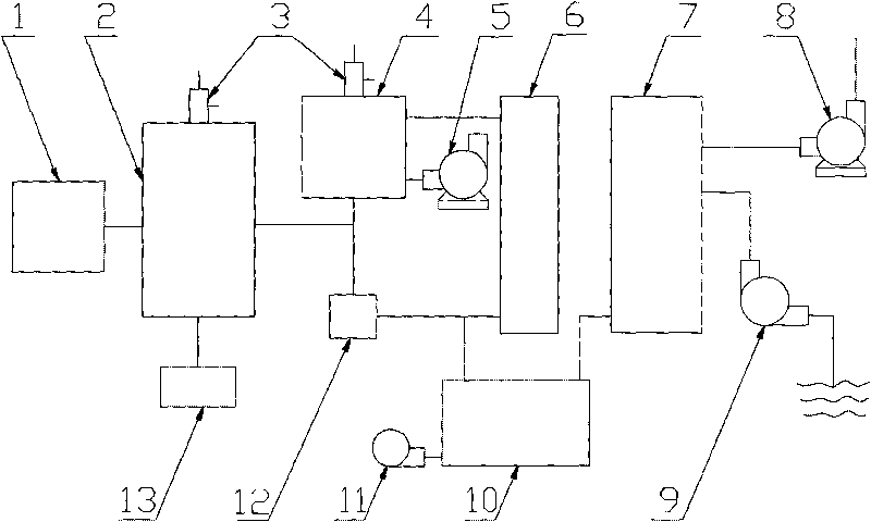
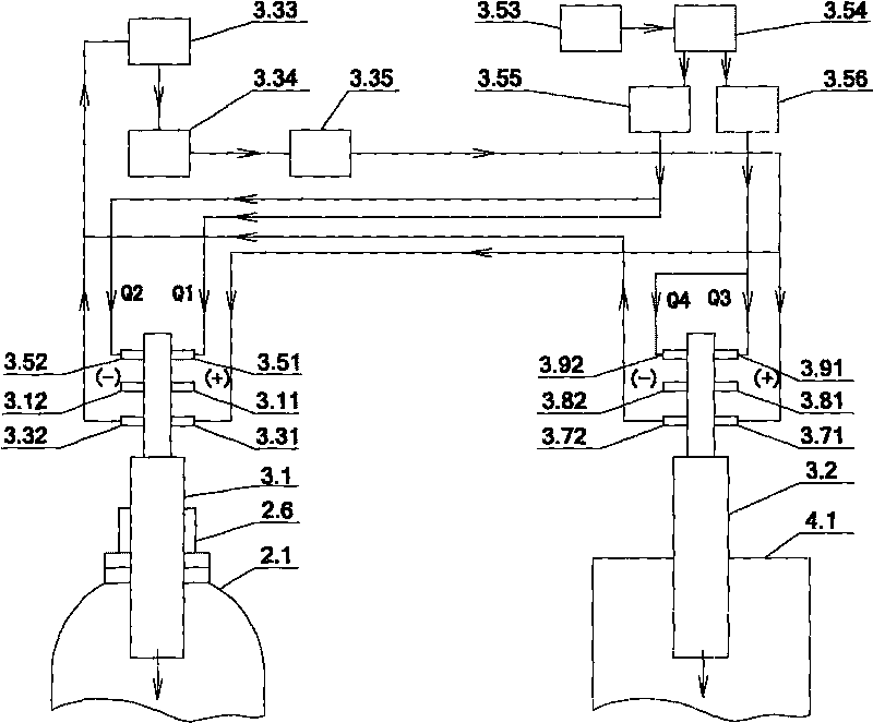
[0047] A thermal plasma incineration device for ship garbage, the overall structure is as follows figure 1 As shown, it includes a feed system 1, an incineration system (including an incinerator 2, a plasma generation system 3 and a second combustion chamber 4), a blower 5, a heat exchanger 6, a desulfurization and dust removal tower 7, an induced draft fan 8, a first water pump 9, Quench cooler 10, second water pump 11, slag extractor 13 and automatic control system. The feeding system is connected to the incineration system through pipelines, and plays the role of temporarily storing garbage and transporting garbage to the incineration system.

[0048] Described below:

[0049] 1. The structure of the feeding system is as follows: F...


PUM


Abstract

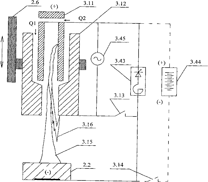
The invention relates to a thermal plasma device for incinerating marine garbage, which comprises a feed system, an incinerator, a plasma system, a secondary combustion chamber, a blast blower, a heat exchanger, a desulfurization and dust removal tower, a draught fan, a first water pump, a quench cooler, a second water pump, a tapping device and an automatic control system. The invention adopts a transferred-arc and non-transferred arc dual-purpose direct-current plasma generator as an incineration heat source, which not only can make full use of a shipborne dynamic power supply (or an accumulator battery) but also can use a non-transferred arc in the initial stage of incineration and adopt the working mode of a transferred arc after a molten pool is molten. Compared with a single non-transferred arc operation mode, the heat transmission property is better, the incineration efficiency is higher, and more energy is saved; in the invention, the secondary combustion chamber adopts plasma heating in a similar way, and the condition that new pollution is generated in the treatment process of secondary combustion is avoided; and by high temperature generated by the plasma generator adopted by the invention, the temperature of the molten pool exceeds 1500 DEG C and is sufficient to enable inorganic substances, slag and heavy metal to be fused together, the inorganic substances, the slag and the heavy metal are solidified in a neutral vitreous body and are not easy to precipitate, the treatment of the garbage is finished by one step, and the thermal ignition loss rate is less than 3%.

Description

technical field [0001] The invention belongs to the technical field of environmental protection and relates to a device for incinerating ship garbage with thermal plasma. Background technique [0002] With the application of thermal plasma technology in the national defense industry and the gradual deepening of military conversion, it has been continuously developed and utilized in metallurgy, casting, processing, surface treatment and manufacturing. At the same time, the technology of incinerating hazardous waste with plasma heating method has gradually been recognized by people and expanded to a wider range of fields. [0003] Commercial ocean-going cargo, passenger ships, offshore operation ships, scientific research ships and military aircraft carriers, submarines, cruisers, destroyers, etc., ships that sail and perform missions at sea for a long time will inevitably produce a lot of domestic garbage and other wastes during the voyage ( Some of them are hazardous waste)...

Claims


Application Information

Patent Timeline
IPC IPC(8): F23G5/10F23G5/16F23G5/44F23J15/06F23J15/04H05H1/46
CPCY02E20/30
Inventor 朱鹏程吴绍强郭秉楠王会明马永华齐峰杨晓东
Owner AEROSPACE ENVIRONMENTAL ENG
Learn More