
Passive terrestrial heat type snow and ice melting device and construction process thereof

A snow melting and geothermal technology, applied to roads, pavement details, roads, etc., can solve the problems that affect the speed of snow and ice melting, reduce heat exchange efficiency, and damage the bearing capacity of road surfaces, so as to save the cost of later maintenance and replacement, save Investment and management costs, effects of good heat transfer performance

Pending Publication Date: 2018-09-04
SHANDONG YATEER GROUP
View PDF13 Cites 6 Cited by
  • Summary
  • Abstract
  • Description
  • Claims
  • Application Information

AI Technical Summary

Problems solved by technology

The heat release pipe adopts a horizontal S-shaped coil, and a third water inlet and outlet pipe is added. The pipeline is long and prone to three problems: first, the resistance along the heating pipeline is increased, and the farthest end of the pipeline is due to the water flow velocity. The decrease of the heat transfer efficiency will reduce the heat transfer efficiency and affect the speed of melting snow and ice; secondly, a large number of pipelines are buried under the pavement, which will cause certain damage to the bearing capacity of the pavement, and due to the characteristics of thermal expansion and contraction, it will cause supply The thermal expansion and contraction of the heat pipe and the airport runway affect the service life of the runway; third, the use of horizontal S-shaped coils increases the connection between the pipes and increases the risk of leakage
The viscosity of ethylene glycol increases under low temperature conditions, which requires an increase in the power consumption of the pump and reduces the efficiency of the entire heat pump system

Method used


Image

  • Passive terrestrial heat type snow and ice melting device and construction process thereof
  • Passive terrestrial heat type snow and ice melting device and construction process thereof
  • Passive terrestrial heat type snow and ice melting device and construction process thereof

Examples


Embodiment Construction

[0065] The present invention will be further described below in conjunction with the accompanying drawings and embodiments.

[0066] The structures, proportions, sizes, etc. shown in the drawings attached to this specification are only used to match the content disclosed in the specification for the understanding and reading of those who are familiar with this technology, and are not used to limit the conditions for the implementation of the present invention , so it has no technical substantive meaning, and any modification of structure, change of proportional relationship or adjustment of size shall still fall within the scope of the disclosure of the present invention without affecting the functions and objectives of the present invention. The technical content must be within the scope covered. At the same time, terms such as "upper", "lower", "left", "right", "middle" and "one" quoted in this specification are only for the convenience of description and are not used to lim...


PUM

PropertyMeasurementUnit
Thicknessaaaaaaaaaa

Abstract

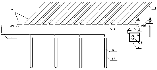
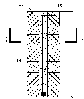
The invention discloses a passive terrestrial heat type snow and ice melting device which comprises a pavement heating pipe group, wherein the pavement heating pipe group is transversely buried on a shallow ground surface; horizontal headers which are parallel to the length direction of a pavement and buried pipe groups which are buried vertically and deeply are arranged on two sides of a pavementto be heated; both the pavement heating pipe group and the buried pipe groups are connected with the horizontal headers; water pumps are mounted on the horizontal headers; the pavement heating pipe group consists of a main pipe and branch pipes; the main pipe is mounted on the outer side of the pavement and is parallel to the length direction of the pavement; the main pipe comprises an outer pipeand an inner pipe which are nested together; an inorganic heat conduction medium layer is arranged between the inner pipe and the outer pipe; the branch pipes are communicated with an inner cavity between the inner pipe and the outer pipe of the main pipe; the horizontal headers are connected with the inner pipe of the main pipe of the pavement heating pipe group; heat accumulated by the horizontal headers is conducted to the inner pipe of the pavement heating pipe group and is used for heating the inorganic heat conduction medium between the inner pipe and the outer pipe; and the heat is conducted to a pavement surface from the branch pipes of the pavement heating pipe group, and thus snow and ice melting can be achieved. The invention further discloses a construction process of the device.

Description

technical field [0001] The invention relates to a road heating technology, in particular to a passive geothermal snow-melting and ice-melting device and its construction technology. Background technique [0002] In the use of large-area open-air facilities such as airport runways, expressways, and municipal roads, ice and snow weather will have a huge impact, ranging from delaying traffic to traffic, and causing safety accidents. Therefore, when the above-mentioned facilities are used in ice and snow weather, snow-melting and thawing operations should be performed. The traditional method is to sprinkle snow-melting and ice-melting agents, but the cost of spraying snow-melting and ice-melting agents is high, causing corrosion to the ground and polluting the environment. [0003] The Chinese invention patent with the patent publication number CN1238721A discloses a superconducting heat transfer medium, which can transfer heat quickly. [0004] The Chinese utility model patent...

Claims


Application Information

Patent Timeline
IPC IPC(8): E01C11/26
CPCE01C11/26
Inventor 王恩琦
Owner SHANDONG YATEER GROUP
Learn More