Eureka AIR delivers breakthrough ideas for toughest innovation challenges, trusted by R&D personnel around the world.

Method for low-voltage thyristor reactive compensation switching of metallurgical electric furnace

A thyristor, electric furnace technology, applied in reactive power compensation, reactive power adjustment/elimination/compensation and other directions, can solve problems such as operating overvoltage, short service life, switching, etc., to achieve fast response speed, extended service life, avoidance of effect of oversupply

Inactive Publication Date: 2010-06-09
四川伟力得能源股份有限公司
View PDF0 Cites 4 Cited by
  • Summary
  • Abstract
  • Description
  • Claims
  • Application Information

AI Technical Summary

Problems solved by technology

[0004] 1: Since the action elements of contactors and circuit breakers are all electromagnetic induction type, they cannot be switched when the voltage and current cross zero due to their action time of about 40-60ms, resulting in a large closing surge current and reducing the capacitor And the service life of actuators such as contactors
[0005] 2: Due to its inherent action characteristics, it is easy to cause operating overvoltage. After opening once, it must wait for the capacitor to discharge (about 3 minutes) before closing the next time. It cannot meet the requirements of fast switching of reactive power compensation during the lifting process of metallurgical electric furnace electrodes. process requirements
[0006] 3: Adopt the method of first cast first cut, the frequency of mechanical action is frequent, and the service life of components is short

Method used


Image

  • Method for low-voltage thyristor reactive compensation switching of metallurgical electric furnace
  • Method for low-voltage thyristor reactive compensation switching of metallurgical electric furnace
  • Method for low-voltage thyristor reactive compensation switching of metallurgical electric furnace

Examples


Embodiment 2

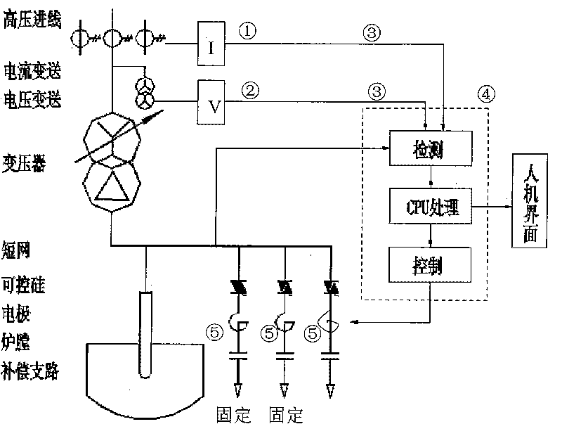
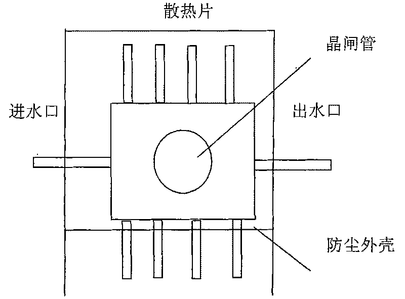
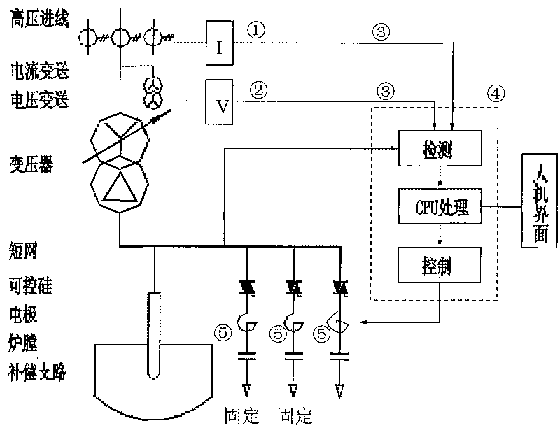
[0028] Such as Figure 1-2 Shown, the application of the present invention is as follows:

[0029] 1. On the terminal block of the switch cabinet at the high voltage side of the metallurgical electric furnace, pass the current transmitter ①, voltage transmitter ②A, B, C three-phase current and voltage signals, and transmit the secondary signal to the input terminal of the controller through the communication wire ③, The controller sends a pulse trigger signal after being processed by the CPU system.

[0030] 2. When the power of the metallurgical electric furnace is less than or equal to 0.9, the pulse signal drives the static fixed switching unit, and when the voltage crosses zero, the thyristors of each phase and group are switched on in sequence according to the time interval of 1 cycle, so that the power factor reaches 0.9.

[0031] 3. When the power of the metallurgical electric furnace reaches 0.9, the controller continues to conduct sampling and analysis, and sends a p...


PUM


Abstract

The invention discloses a method for the low-voltage thyristor reactive compensation switching of a metallurgical electric furnace, which comprises: firstly, dividing capacitors and reactor groups in a reactive compensation device into a plurality of groups according to A, B, C phases under a condition that the current in each group is less than or equal to 200 amperes, wherein two thirds of the capacity of each phase is fixed switching; assembling a thyristor and a trigger circuit with a radiating fins, wherein the radiating fins adopt a water cooling circulation mode; connecting and fixing the thyristor, the capacitors and reactors by using copper conductors to form a group of thyristor ractive compensation switching unit; and finally, determining the number of static fixed thyristor switching compensation unit groups by using a thyristor reactive compensation switching controller according to a requirement that a power factor cos phi is equal to 0.9. The method has the advantages that: the demands for reactive compensation are satisfied when the normal production process conditions of the metallurgical electric furnace are met; the service life of the device is prolonged; the possibilities for undercompensation are eliminated; and overcompensation is avoided.

Description

technical field [0001] The invention relates to a control method of an actuator in a low-voltage reactive power compensation device of a metallurgical electric furnace, in particular to a method for reactive power compensation switching of a low-voltage thyristor of a metallurgical electric furnace. Background technique [0002] Metallurgical electric furnace is a kind of high energy consumption equipment, which is mainly divided into more than 20 series such as calcium carbide, industrial silicon, ferrosilicon, ferromanganese, ferronickel, and yellow phosphorus. When the equipment is in production and operation, the voltage is low, the current is large, and the electrodes need to be adjusted continuously according to the furnace conditions. The load changes rapidly. Because of the low power factor (0.7-0.86 or so), it is necessary to install a reactive power compensation device for compensation. [0003] Traditional high and low voltage compensation devices mainly use conta...

Claims


Application Information

Patent Timeline
Patent Type & Authority Applications(China)
IPC IPC(8): H02J3/18
CPCY02E40/30
Inventor 陈继军
Owner 四川伟力得能源股份有限公司
Why Eureka
Eureka Blog
Learn More