
Hybrid current collector used for lead storage batteries

A lead-acid battery and current collector technology, applied in electrode carriers/current collectors, battery pack components, circuits, etc., can solve problems such as large overload current on the interface surface, hydrogen evolution and capacity loss, insufficient mechanical strength, etc., and achieve material cost. Low, high weight-to-energy, light-weight effect

Inactive Publication Date: 2010-04-14
东莞恒量新能源科技有限公司 +1
View PDF0 Cites 8 Cited by
  • Summary
  • Abstract
  • Description
  • Claims
  • Application Information

AI Technical Summary

Problems solved by technology

In a similar way, lead can also be plated on felt polymer fibers, or lead can be covered by electroplating, immersion plating and spray plating on copper grids. Such industrial methods are similar to the lead coating on the surface of coaxial lead-plated glass fiber filaments , only to overcome the shortcomings of insufficient mechanical strength of lead-coated glass fiber wire woven lead cloth
However, there are also many problems with this type of lead-covered grid, for example: the current-collecting welding problem of the lead (tab) of the lead-coated material on the surface of plastic or felt-like polymer fibers, because the current-collecting bridge is usually made of lead alloy material , the fusion and solidification of two different materials has become the key technology
In addition, the tabs manufactured by the lead-coated process are prone to problems caused by corrosion in sulfuric acid mist due to the large overload current on the interface surface
Especially the copper grid covered with lead, because copper is unstable in the positive potential area, if the lead plating layer has defects, it will cause the copper to dissolve in the sulfuric acid solution, and then deposit on the surface of the negative active material, resulting in hydrogen evolution and capacity loss

Method used


Image

  • Hybrid current collector used for lead storage batteries
  • Hybrid current collector used for lead storage batteries
  • Hybrid current collector used for lead storage batteries

Examples


Embodiment 1

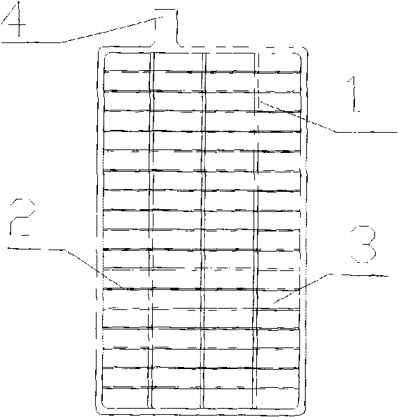
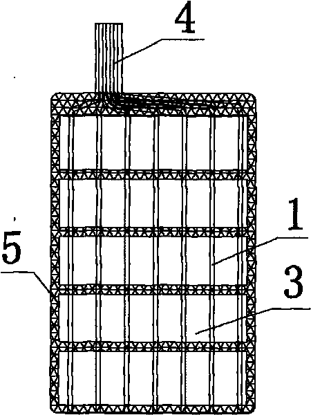
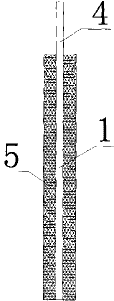
[0056] A hybrid current collector with a shape similar to a conventional grid was produced, and the current collector was designed as a rectangle with a width of 50 mm and a length of 72 mm, and a thickness of 2.5 mm. Firstly, the lead alloy skeleton is made by cold rolling or hot casting, and the side structure of the skeleton is as follows: image 3 As shown, 6 vertical ribs 1 are set, and the vertical ribs are circular with a diameter of 2mm, without horizontal bars 2, and the extension shape of the vertical ribs is also used as a pole ear 4, and the height of the pole ears is 12mm. The lead alloy skeleton is thermoformed with ABS plastic 5 in a special mold. The plastic frame includes four frames and four horizontal bars in the frame. The frame width of the four frames is 1.5mm, the width of the horizontal bars is 1.2mm, and the thickness is 2.5mm. Figure 6 As shown, the shape and structure of the current collector after thermoplastic molding is shown in FIG. 2 . The wei...

Embodiment 2

[0058] The pole lug described in embodiment 1 and the lead alloy skeleton are deformed, and the pole lug 4 is made as an attached Figure 4 The integrated structure shown is similar to the lead alloy skeleton, only the vertical rib 1 is designed, and there is no horizontal bar 2, which is similar to the thermoplastic molding method of ABS plastic 5. The shape and structure of the current collector after thermoplastic molding are as follows: Except for the integrated structure, the implementation effect is similar to that of Embodiment 1.

[0059] Since the thermoplastic molding of the four frames of the grid in Embodiment 1 and Embodiment 2 is ABS plastic, the auxiliary current collection capacity of the left and right vertical frames is lost. To strengthen the current collection capacity of the current collector, lead The surface area of ​​the vertical rib 1 of the alloy skeleton is increased, or further technical improvement is implemented.

Embodiment 3

[0061] The frame surface of the ABS plastic 5 described in embodiment 2 and the lead alloy skeleton thermoplastic molding is processed into a regular concave-convex surface, and the thickness (maximum value) between the convex surfaces on both sides is 2.5mm, and the two sides are electroplated and dipped. , spraying and other conventional industrial methods cover a layer of lead on the plastic surfaces on both sides, so that the surface of the hard plastic 5 is changed into a lead-coated layer. In this embodiment, because the surface of the ordinary hard plastic is changed to lead-coated, the contact area between the current collector and the electroactive material is increased, the current collection capacity of the current collector is strengthened, and the large current charge and discharge capacity of the plate is improved. improve.


PUM

PropertyMeasurementUnit
thicknessaaaaaaaaaa
thicknessaaaaaaaaaa

Abstract

The invention discloses a hybrid current collector used for lead storage batteries, which is characterized in that the hybrid current collector comprises at least one conducting framework and a shaping framework, the conducting framework is molded in a hybrid form, the shaping framework is manufactured by lightweight hard materials, and the hybrid current collector is a grid plate with hollow grids or a plate-shaped current collector without grids. The hybrid process of the conducting framework and the shaping framework includes injection molding and joggle fixing molding, wherein the injection molding utilizes thermal plastic and cold extrusion or uses cement concrete, the joggle fixing comprises steps of utilizing the lightweight hard material to manufacture a substrate module which is used as the shaping framework and then joggling and fixing the shaping framework with the conducting framework which is designed as a coupling module. The conducting framework of the current collector can extend to form an integrated lead electrode or is electrically fixedly connected with a split lead electrode. The polar plate manufactured by utilizing the current collector is light in weight, high in specific energy, simple in manufacture and low in material cost.

Description

technical field [0001] The invention relates to a pole plate for a lead storage battery, in particular to a mixed aggregate current collector for a lead storage battery. The current collector is light in weight, low in material cost and high in weight specific energy. Background technique [0002] Lead-acid batteries are currently the most widely used type of batteries in the market. They have a wide range of sources of materials and low prices. They have the advantages of safety, reliability, large capacity, and high discharge intensity. Among many batteries, only lead-acid batteries have a recycling efficiency as high as 96~ 99%, the material resources can be recycled almost completely. In the context of the continuous consumption of material resources, lead-acid batteries have gained more and more extensive markets in recent years. [0003] Lead-acid batteries consist of shells, pole plates, separators and electrolytes, and the pole plates are made of current collectors a...

Claims


Application Information

Patent Timeline
Patent Type & Authority Applications(China)
IPC IPC(8): H01M4/70H01M4/82H01M2/28H01M4/68H01M50/541
CPCY02E60/12Y02E60/10
Inventor 刘粤荣陈方
Owner 东莞恒量新能源科技有限公司
Learn More