Organic electroluminescence element and method of manufacturing the same
An electroluminescent element and electroluminescent technology, which are applied to electroluminescent light sources, electrical components, organic semiconductor devices, etc., can solve the problems of plasma damage, difficulty in injecting electrons, and inability to obtain component characteristics, so as to improve the extraction efficiency, Excellent color rendering effect
- Summary
- Abstract
- Description
- Claims
- Application Information
AI Technical Summary
Problems solved by technology
Method used
Image
Examples
Embodiment 1
[0072] By the following method, produced by figure 1 An organic EL transparent element having a layer structure as shown.
[0073] (transparent substrate 1, anode layer 2)
[0074] First, in the order of ultrasonic cleaning using pure water and surfactant, running water cleaning using pure water, ultrasonic cleaning using a 1:1 mixed solution of pure water and isopropanol, and boiling cleaning using isopropanol, the The glass substrate on which the patterned transparent conductive film (ITO) was formed with a film thickness of 300 nm was cleaned. The substrate was slowly pulled up from boiling isopropanol and dried in isopropanol vapor, followed by a UV-ozone cleaning.
[0075] The substrate was used as the anode 1, placed in a vacuum chamber, and evacuated to 1×10 -6 Torr, each molybdenum boat (molybdenum boat) filled with vapor deposition materials and a vapor deposition mask for film formation in a predetermined pattern are set in advance in the vacuum chamber, and the b...
Embodiment 2
[0099] On the ITO (100nm) of the cathode layer of the transparent element produced in Example 1, titanium oxide (anatase (anatase) type manufactured by Kanto Chemical Co., Ltd.: particle size 0.1-0.3 μm) and fluorine oil were directly coated. (fluorinated oil) (Demnums-20 manufactured by Daikin Industries, Ltd.) was dehydrated and degassed at a low dew point (low dew point) and mixed to form a light-diffusing reflective layer with a film thickness of 200 μm.
[0100] Using UV curable resin, it is sealed with another glass plate to obtain an organic EL element.
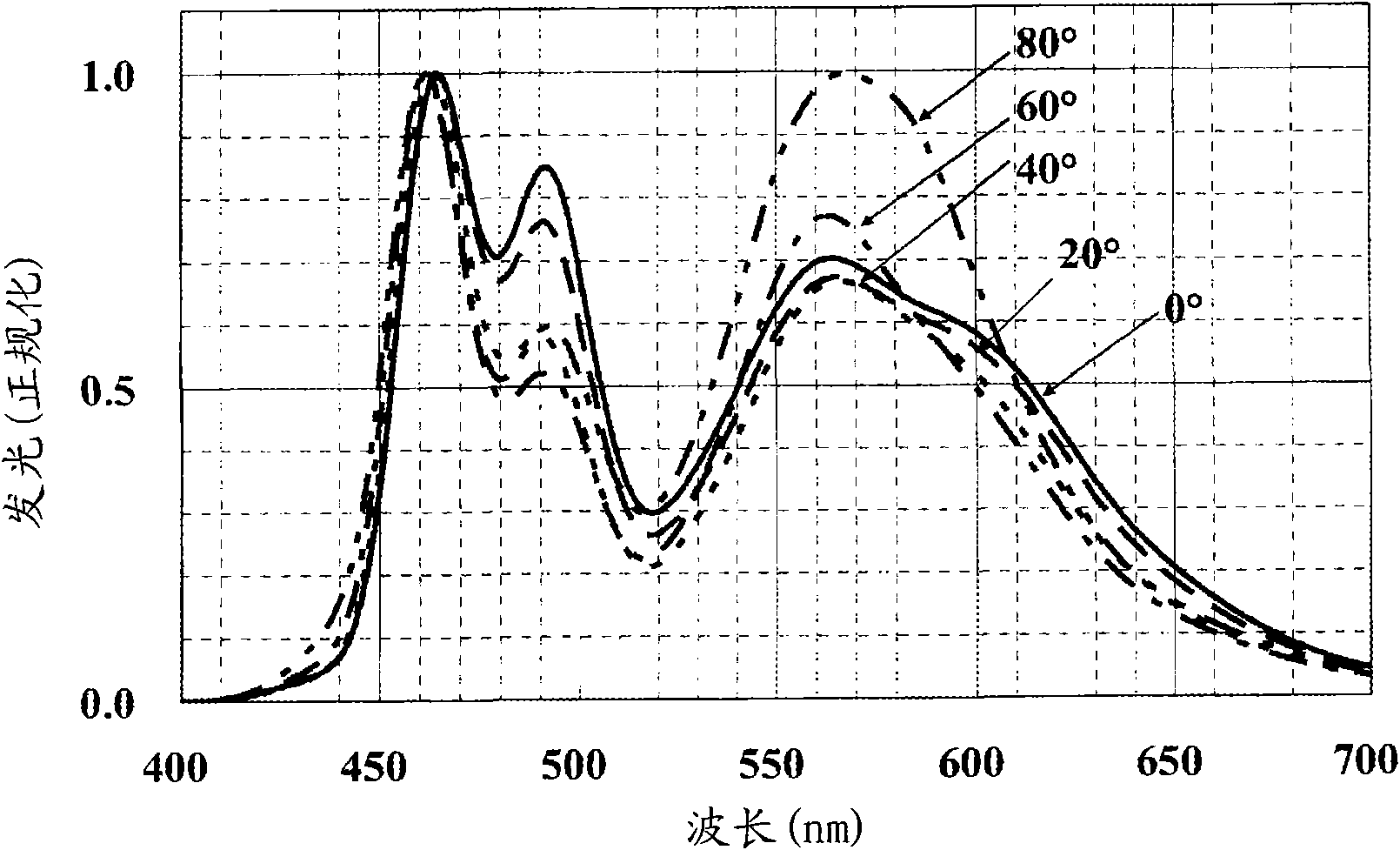
[0101] image 3 A graph showing the results of evaluating the angular dependence of the spectrum of this element is shown in .
[0102] from figure 2 , 3 It can be confirmed by comparison that, in the case where a light-diffusing reflective layer is provided (Example 2, figure 2 ), the angular dependence of the spectrum is suppressed, and the same color can be seen from all angles.
[0103] In addition, it can b...
Embodiment 3
[0105] By the same method as in Example 1, each electrode layer and light-emitting unit were formed, and four light-emitting units were stacked via the second charge generation layer, and then, by the same method as in Example 2, a light-diffusing reflective layer was formed to produce a multi-layer battery. Organic EL element with photonic structure.
[0106] For the second charge generation layer, Liq was used as an electron-donating substance, and a material of DPB:Liq=75:25 was formed with a film thickness of 17 nm, and aluminum (Al ) into a film, and then, as an electron-accepting substance, MoO 3 The film is formed and formed between each unit.
[0107] When the layer structure of the device is simplified, it is ITO (300nm) / MoO 3 (5nm) / / first unit (blue)[NS21(15nm) / EB43:EB52(30nm,98.8:1.2) / BAlq(5nm)] / / DPB:Liq(17nm,75:25) / Al(0.5nm ) / MoO 3 (2nm) / / The second unit (yellow+blue) [NS21(15nm) / NS21:EY52(20nm, 98.7:1.3) / EB43:EB52(30nm, 98.8:1.2) / BAlq(5nm)] / / DPB: Liq(17nm, 75...
PUM
 Abstract
Description
Claims
Application Information
 - R&D
- Intellectual Property
- Life Sciences
- Materials
- Tech Scout
- Unparalleled Data Quality
- Higher Quality Content
- 60% Fewer Hallucinations
Browse by: Latest US Patents, China's latest patents, Technical Efficacy Thesaurus, Application Domain, Technology Topic, Popular Technical Reports.
© 2025 PatSnap. All rights reserved.Legal|Privacy policy|Modern Slavery Act Transparency Statement|Sitemap|About US| Contact US: help@patsnap.com


