
Pressure-swing absorber

A technology of pressure swing adsorption and air inlet pipe, which is applied in the separation of dispersed particles, chemical instruments and methods, separation methods, etc., can solve the problems of increasing investment costs, reducing the efficiency of adsorbents, and uneven distribution of the diameter of adsorption towers. Improve utilization efficiency, ideal treatment effect, and promote the effect of realization

Inactive Publication Date: 2010-02-17
北京健坤伟华新能源科技有限公司
View PDF0 Cites 12 Cited by
  • Summary
  • Abstract
  • Description
  • Claims
  • Application Information

AI Technical Summary

Problems solved by technology

[0004] In the pressure swing adsorption process, the gas adsorption process is carried out in the adsorption tower. Generally, the diameter of the adsorption tower is relatively larger than that of the gas inlet pipe. After the gas enters the adsorption tower, it is unevenly distributed along the diameter direction in the adsorption tower. Reduced effective sorbent efficiency
However, if the adsorption capacity is ensured by increasing the adsorption space and increasing the volume of the adsorber, the investment cost will inevitably increase.

Method used


Image

  • Pressure-swing absorber
  • Pressure-swing absorber

Examples


Embodiment 1

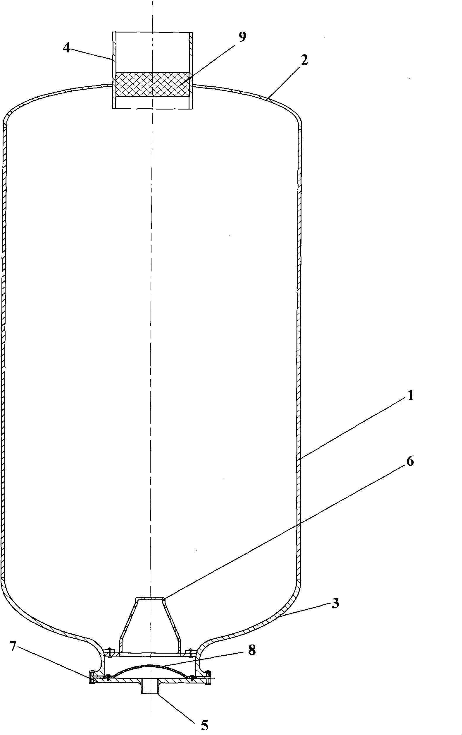
[0024] Such as figure 1 As shown, an adsorption tower includes: a cylindrical cylinder body 1, an upper head 2 and a lower head 3, an outlet pipe 4, an air inlet pipe 5, a gas distribution device 6, and an end cover 7, wherein:

[0025] The upper head 2 and the lower head 3 are respectively arranged at the two ends of the cylinder body 1 where the adsorbent is placed. side, and the end cover 7 is provided with an air inlet pipe 5, thus, the air outlet pipe 4, the upper head 2, the cylinder body 1, the lower head 3, the end cover 7 and the air inlet pipe 5 jointly form an internal cavity, only the The cavity communicates with the outside only through the outlet pipe 4 and the inlet pipe 5;

[0026] A gas distribution device 6 is arranged above the intake pipe 5. Diagrammatically, the gas distribution device 6 is fixed on the lower head 2, which is an inverted "cup"-shaped structure formed by bending a flat plate several times. Moreover, several through holes are arranged on t...

Embodiment 2

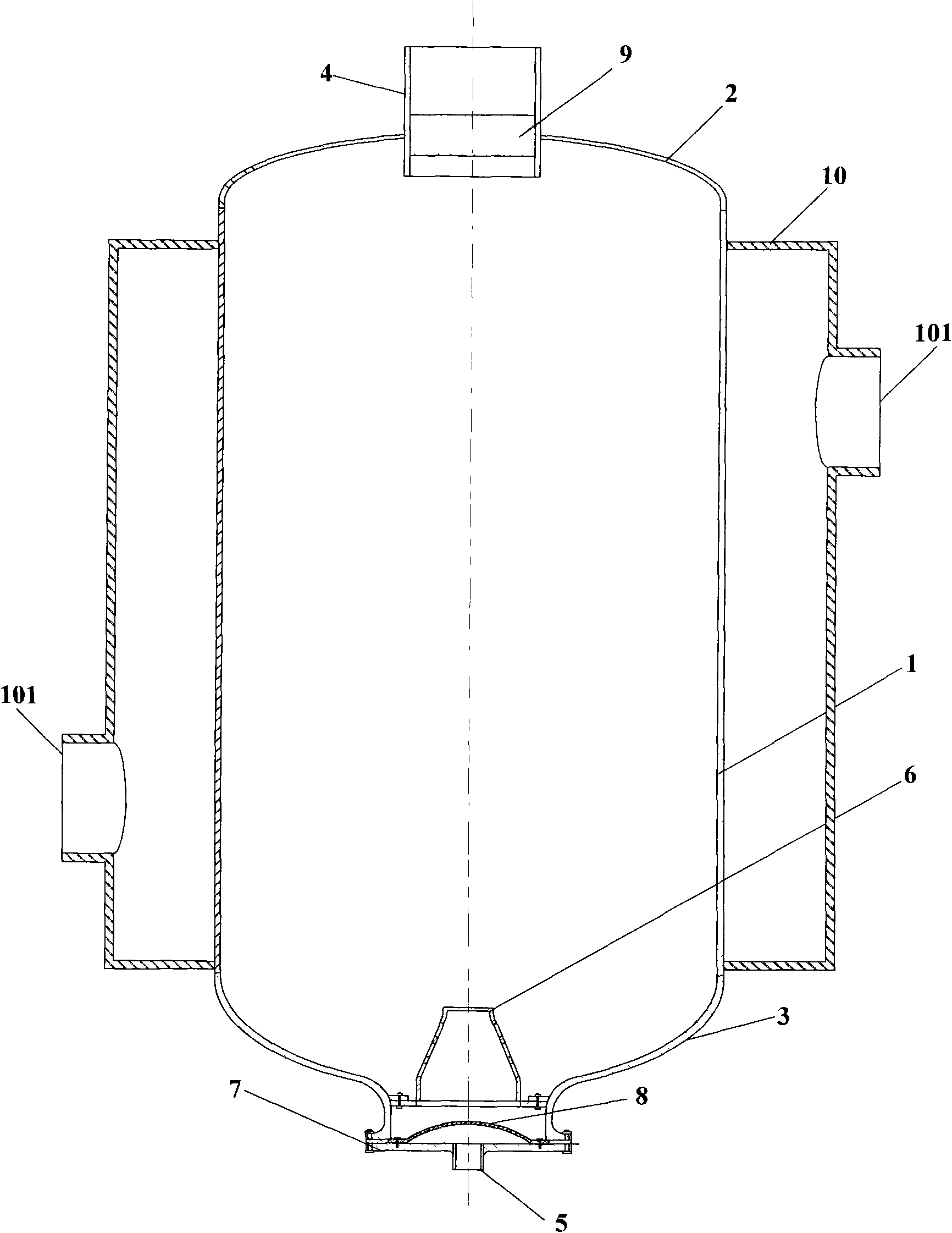
[0036] Such as figure 2 Shown is a schematic cross-sectional view of another pressure swing adsorption tower, compared with the pressure swing adsorption tower shown in Embodiment 1, a sleeve 10 is added, and the sleeve 10 is arranged on the outside of the cylinder 1, and is connected to the A hollow cavity that allows fluid flow is formed between the outer surfaces of the cylinder body 1, and the sleeve 10 can be fixed on the outside of the cylinder body 1 by direct welding, or can be fixed on the outside of the cylinder body 1 through internal connecting ribs (not shown). The connection is fixed. Moreover, the sleeve 10 is provided with two connection nozzles 101 communicating with the outside.

[0037] During the actual use of the pressure swing adsorption tower, a heat exchange fluid is introduced from a connecting nozzle 101, and the fluid exchanges heat with the cylinder body 1 in the hollow cavity formed between the sleeve 10 and the cylinder body 1, thereby To affec...


PUM


Abstract

The invention discloses a pressure-swing absorber comprising a cylinder fixedly provided with an upper end enclosure and a lower end enclosure. The upper end enclosure is fixedly provided with a gas outlet pipe; the pressure-swing absorber further comprises an end cover and a gas distributor; the end cover is fixedly connected with a lower sealing cover and fixedly provided with a gas inlet pipe;the gas outlet pipe, the upper end enclosure, the cylinder, the lower end enclosure, the end cover and the gas inlet pipe jointly form an internal hollow cavity which is communicated with the outsideonly through the gas outlet pipe and the gas inlet pipe; the gas distributor is provided with a plurality of through holes with outlets facing to different directions of the internal part of the cylinder; and the gas inlet pipe is communicated with the internal cylinder through the through holes. The pressure-swing absorber has the following advantages: (1) the situation of uneven distribution ofraw material gas in the pressure-swing absorber along the diameter direction and the utilization rate of absorbent are both improved; (2) gas filtering devices are arranged at a raw material gas inletend and a purification gas outlet end so that the treatment effect is more perfect; and (3) the treatment capacity of the absorbent is improved by adopting a nested design.

Description

technical field [0001] The invention relates to gas purification, in particular to a pressure swing adsorption tower. Background technique [0002] Pressure Swing Absorption (PSA) technology uses the difference in the adsorption capacity of different components in the gas medium on the adsorbent to realize the separation and purification of the gas. The adsorbent performs selective adsorption when the pressure rises. Desorption regeneration is obtained when the pressure is reduced. Pressure swing adsorption technology was invented by Skarstrome et al. in 1960. In the past 30 years, PSA technology has won more and more attention due to its lower investment cost and energy consumption. In our country, the research on this technology started in the 1970s. Initially, PSA technology was mainly used in air drying and hydrogen purification. In the past ten years, this technology has been rapidly promoted and applied in chemical industry, metallurgy, electronics, medicine, food an...

Claims


Application Information

Patent Timeline
Patent Type & Authority Applications(China)
IPC IPC(8): B01D53/047
Inventor 邓舟夏洲胡益铭田玲张妍张丽颖
Owner 北京健坤伟华新能源科技有限公司
Learn More