
Flyback power converter and loop control method thereof

A power converter, flyback technology, applied in control/regulation systems, output power conversion devices, instruments, etc., can solve the slow loop transient response of flyback power converters, output voltage overshoot, etc. problem, to achieve the effect of reducing time, small undershoot voltage, and improving response speed

Active Publication Date: 2010-02-10
BEIJING VIMICRO ARTIFICIAL INTELLIGENCE CHIP TECH CO LTD
View PDF5 Cites 27 Cited by
  • Summary
  • Abstract
  • Description
  • Claims
  • Application Information

AI Technical Summary

Problems solved by technology

Due to the delay accumulated by multiple cycles in the prior art, the loop transient response of the flyback power converter will be slow, and large output voltage overshoot (Overshoot) and undershoot (Undershoot) phenomena will be generated, namely Existing technology takes more time to reach the final steady state

Method used


Image

  • Flyback power converter and loop control method thereof
  • Flyback power converter and loop control method thereof
  • Flyback power converter and loop control method thereof

Examples


Embodiment Construction

[0067] In order to make the above objects, features and advantages of the present invention more comprehensible, the present invention will be further described in detail below in conjunction with the accompanying drawings and specific embodiments.

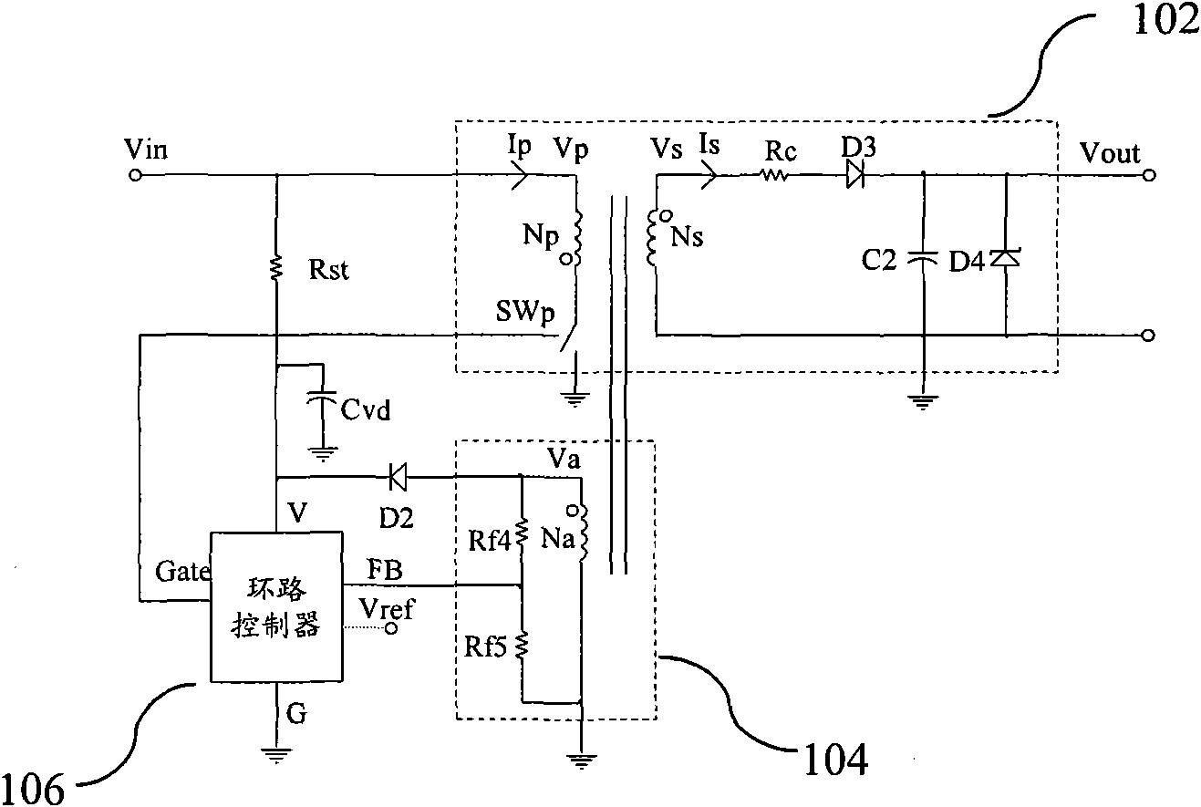
[0068] refer to figure 1 The structure diagram of the flyback power converter shown mainly includes a switch circuit 102, a feedback voltage sampling circuit 104 and a loop controller 106, wherein the switch circuit 102 includes an isolated primary inductor Np and a secondary inductor Ns, and the main The primary side also includes a switch SWp, and the secondary side also includes a parasitic resistance Rc, a diode D3, a capacitor C2 and a diode D4; the feedback voltage sampling circuit 104 includes an auxiliary stage inductor Na and two voltage dividing resistors Rf4 and Rf5; a loop controller 106 It controls the turn-on and turn-off of the primary side switch SWp.

[0069] In practice, the inductor is a coil of copper wire wou...


PUM


Abstract

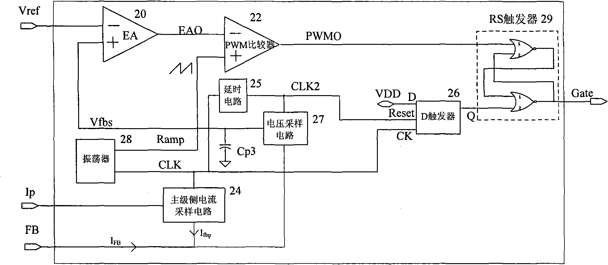
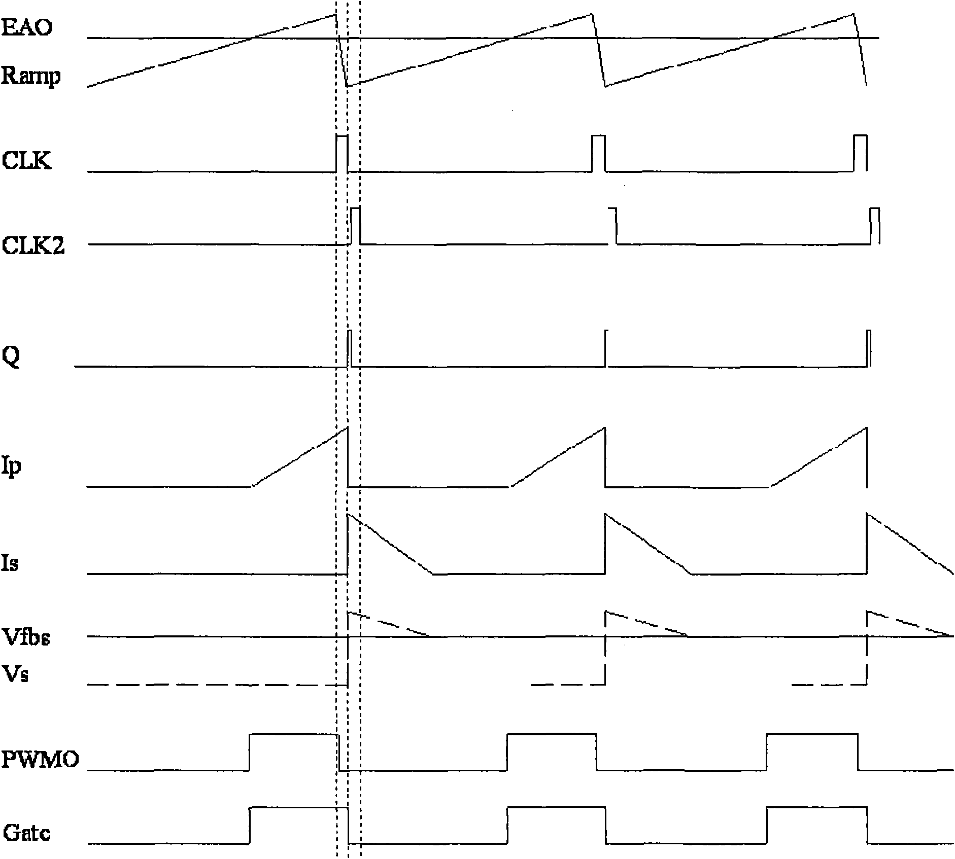
The invention provides a flyback power converter, comprising a primary side current sampling unit for sampling a primary side switching current signal at a fast edge of a preset asymmetrical sawtooth wave signal Ramp and superposing the signal to an auxiliary-level voltage feedback node FB; a pulse-width control unit for closing a primary side switch when a slow edge of the Ramp starts; a conducting time point for adjusting the primary side switch according to a pulse-width modulation signal PWMO; and a modulation unit working at the slow edge of the Ramp comprises the following subunits: a feedback voltage sampling subunit for sampling a feedback voltage Vfb superposed with the primary side switching current signal from the FB; a voltage contrast subunit for enlarging the difference between the feedback voltage Vfb and a reference voltage Vref to obtain an error voltage EAO; and a pulse-width contrast subunit for comparing the pulse width of the error voltage EAO and the Ramp to obtain the PWMO. The flyback power converter can increase the transient response speed of a loop so as to quickly adjust the loop to a final stable state.

Description

technical field [0001] The invention relates to the field of circuit control, in particular to a flyback power converter, a loop control method of the flyback power converter and an AC-DC converter. Background technique [0002] The flyback power converter (Flyback Power Converter) is mostly used in AC-DC and DC-DC converters to realize the function of voltage conversion. In order to meet safety standards and prevent electric shock on the secondary side under abnormal conditions, the flyback power converter Power converters usually use an isolated structure. There are two ways to achieve complete isolation: the first is to feed back the voltage signal on the secondary side to the primary side through an optocoupler, and then perform switch control on the primary side; the second is to approximately sample the secondary side through an auxiliary stage. The voltage on the stage side; but due to the high cost of the optocoupler, the first method is gradually replaced by the se...

Claims


Application Information

Patent Timeline
Patent Type & Authority Applications(China)
IPC IPC(8): H02M7/04G05F1/10H03K3/017H03K7/08
CPCH02M3/33523
Inventor 王钊董贤辉杨喆杨晓东
Owner BEIJING VIMICRO ARTIFICIAL INTELLIGENCE CHIP TECH CO LTD
Learn More