Circuit structure for collecting sensor signal of catalytic combustion type fuel gas

A gas sensor and acquisition circuit technology, applied in the direction of material resistance, etc., can solve problems such as danger, sensor zero drift cannot determine the progressive zero drift and zero drift range, single-chip microcomputer can not determine the real zero point of the sensor, etc., to eliminate safety hazards and reduce production /debugging the effect of workload

Inactive Publication Date: 2010-01-20
李晓村
View PDF0 Cites 2 Cited by
  • Summary
  • Abstract
  • Description
  • Claims
  • Application Information

AI Technical Summary

Problems solved by technology

The problem is: since the AD converter and the single-chip microcomputer are sequentially connected behind the differential amplifier 1AN1, the original level value has been eliminated in the obtained signal, so the real level of the two output terminals of the sensor cannot be sensed, that is, the single-chip microcomputer cannot determine the level of the sensor. (Its "automatic zero adjustment" is only digital addition and subtraction in the single-chip microcomputer 1AN3, which does not really eliminate the zero drift of the sensor), so it is impossible to determine the progressive zero drift and the total zero drift range, and the single chip microcomputer is "blinded" up
[0009]2. Progressive zero drift refers to the zero drift that is unidirectional and accumulates over time. The zero drift caused by the deformation of the material, the drift range is unlimited and cannot be determined in advance, so it is more dangerous

Method used


Image

  • Circuit structure for collecting sensor signal of catalytic combustion type fuel gas
  • Circuit structure for collecting sensor signal of catalytic combustion type fuel gas
  • Circuit structure for collecting sensor signal of catalytic combustion type fuel gas

Examples


Embodiment Construction

[0026] The present invention will be further described below in conjunction with drawings and embodiments.

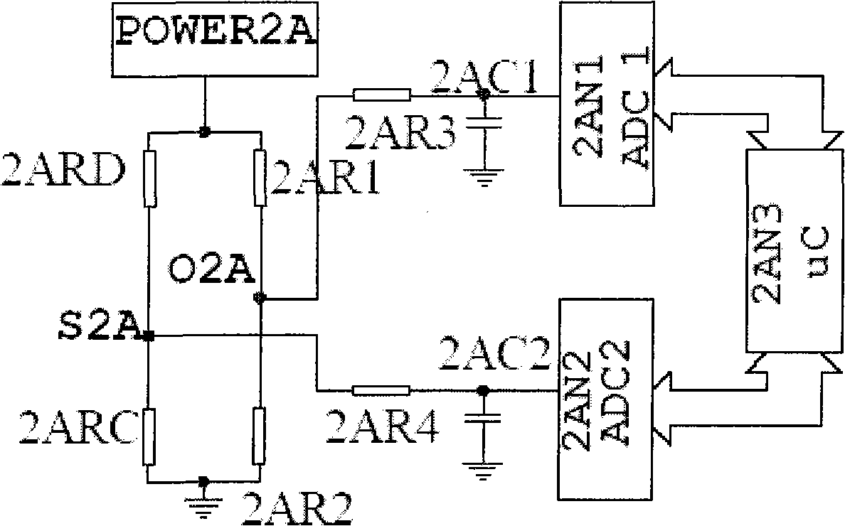
[0027] Such as Figure 2A As shown, the two output terminals O2A and S2A of the sensor are respectively connected with high-resolution AD converters 2AN1 and 2AN2 through the filter circuit, and the output of the AD converters 2AN1 and 2AN2 is sent to the single-chip microcomputer 2AN3.

[0028] Suppose: the potential of O2A point is Vo

[0029] The potential at point S2A is Vs

[0030] Ideally, 2AR1 = 2AR2, Vs-Vo = 0, and the sensor is perfectly balanced. The actual situation is that the sensor that has been continuously energized and aged before leaving the factory (generally 5-7 days) tends to be stable within 5 minutes of being energized at the commissioning site. Since 2AR1 and 2AR2 have high matching accuracy, good symmetry and thermal tracking, it can be considered that Vo at this time is the real zero position of the sensor, and Vs-Vo at this time is the init...


PUM


Abstract

The invention relates to a circuit structure for collecting the sensor signal of catalytic combustion type fuel gas, which comprises two independent single-end signal collecting circuits. The independent single-end signal collecting circuits are two A / D converters or two electronic switches and an A / D converter; digital interfaces of the A / D converters are connected with a first single chip microcomputer, and an analog interface is respectively connected with two output ends of fuel gas sensors; the two electronic switches and the A / D converter are accommodated in a second single chip microcomputer or an independent single / multiple A / D integrated circuit chip, the second single chip microcomputer controls the selection of the two electronic switches through an address line; one end of each electronic switch is respectively connected with two output ends of the fuel gas sensors, and the other end of the electronic switch is connected with the A / D converter. The invention has the advantages of judging the true null shift amplitude and the property of the sensors in time for corresponding treatment and realizing complete number automatic zero set.

Description

technical field [0001] The invention relates to a signal acquisition circuit, in particular to a circuit structure for signal acquisition of a catalytic combustion type combustible gas sensor. Background technique [0002] Catalytic combustion combustible gas sensors (hereinafter referred to as sensors) are used in oil refining, chemical industry, medicine, metallurgy and other industries that require continuous monitoring of combustible gases. Sensitive to flammable gas) and other advantages, it has been widely used in ensuring the safety of production in related industries. [0003] The principle is: to Figure 1A The circuit shown is an example. The sensor is composed of a Wheatstone bridge composed of resistors 1ARC, 1ARD, 1AR1, and 1AR2 in the figure. The resistors 1AR1 and 1AR2 are resistors with good stability and equal nominal values. The resistors 1ARC and 1ARD Platinum resistors in the shape of a sphere are selected and paired with the same material, wire diameter...

Claims


Application Information

Patent Timeline
IPC IPC(8): G01N27/16
Inventor 李晓村
Owner 李晓村
Why Eureka
Try Eureka