
Remote all-optical synchronous optical parameter chirped pulse amplification laser system

A technology of optical parameters and chirped pulses, applied in lasers, laser components, laser components, etc., can solve the problem of restricting the applicable environment of OPCPA amplification systems, affecting optical synchronization and system stability, stability and all-optical synchronization hazards and other issues to achieve the effect of remote OPCPA amplification control, reducing instability and environmental impact on optical transmission, and flexible design

Inactive Publication Date: 2009-10-14
SHANGHAI INST OF OPTICS & FINE MECHANICS CHINESE ACAD OF SCI
View PDF2 Cites 10 Cited by
  • Summary
  • Abstract
  • Description
  • Claims
  • Application Information

AI Technical Summary

Problems solved by technology

For the seed source, the oscillator has the disadvantages of large size, poor frequency stability, and large time jitter, which often bring great harm to the stability and all-optical synchronization of the optical parametric chirped pulse amplification laser system.
Moreover, when the seed pulse is transmitted in space, due to the poor stability of the optical frame and the influence of the environment, the shape of the optical pulse will change, accompanied by large time jitter, etc. These unfavorable factors will seriously affect the optical parameters. The optical synchronization and system stability of the chirped pulse amplification laser system also limit the applicable environment of the OPCPA amplification system

Method used


Image

  • Remote all-optical synchronous optical parameter chirped pulse amplification laser system
  • Remote all-optical synchronous optical parameter chirped pulse amplification laser system

Examples


Embodiment Construction

[0029] The present invention will be further described below in conjunction with the embodiments and accompanying drawings, but the protection scope of the present invention should not be limited thereby.

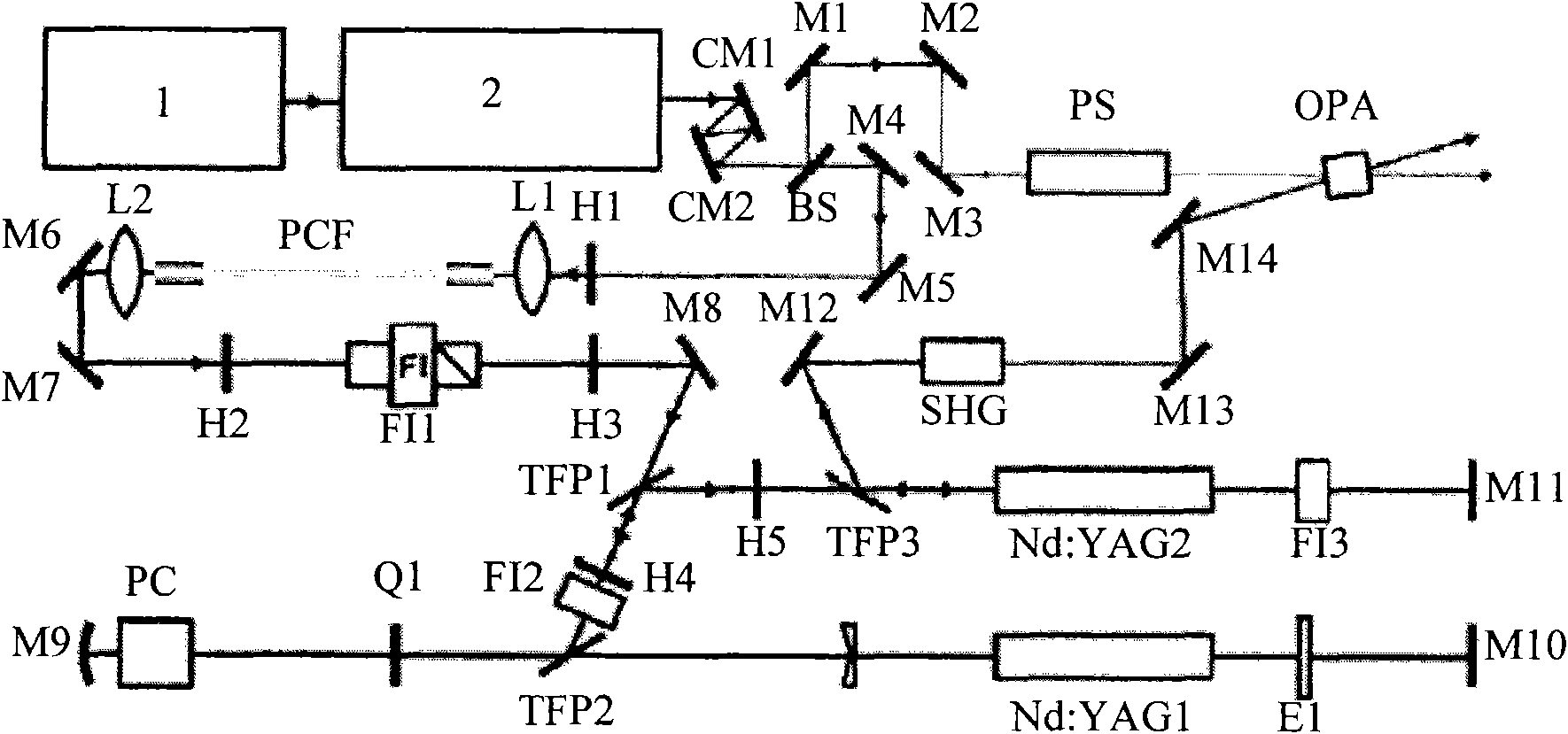
[0030] see figure 1 , figure 1 It is a structural schematic diagram of the remote all-optical synchronous optical parametric chirped pulse amplification laser system of the present invention. It is also a structural schematic diagram of an embodiment of the present invention. Depend on figure 1 It can be seen that the remote all-optical synchronous optical parametric chirped pulse amplification laser system of the present invention consists of a 1550nm femtosecond laser fiber laser 1, a fiber coupler 2, a first fiber and fiber connector 3, a photonic crystal fiber frequency converter 4, and a regenerative amplifier 5. Frequency doubling crystal 6, reflector 7, second optical fiber and optical fiber connector 8, optical fiber stretcher 9, third optical fiber and optica...


PUM


Abstract

A remote all-optical synchronous optical parameter chirped pulse amplification laser system comprises a 1550nm femtosecond fiber laser, a fiber coupler, a transmission fiber and a fiber connector, a fiber frequency converter, a regenerative amplifier, a frequency-doubling crystal, a fiber stretcher, a optical parameter amplifier and a compressor. The invention is characterized in that signal light and pump light source come from the same fiber laser, leading to the great stability, and the fiber transmission in the system is used for replacing the transmission in the air, realizing the control on the remote laser transmission and remote optical parameter chirped pulse amplification, ensuring the synchronization of the high precisions of signal light pulses and pump light pulses of sub-10 femtosecond magnitude and achieving the high-precision control on luminous beam structure. The invention has the advantages of stable system, simple structure, great flexibility, and easy application and integration with a remote OPCPA amplification system.

Description

technical field [0001] The invention relates to a remote all-optical synchronous optical parametric chirped pulse amplification (hereinafter referred to as OPCPA) excitation Background technique [0002] The rapid development of femtosecond laser amplification technology in the past few years has provided unprecedented practical means and development opportunities for human beings to fully explore microscopic ultrafast phenomena and study strong field physics. In particular, the emergence of ultra-strong and ultra-short femtosecond laser, because it has ultra-high peak power and ultra-short pulse width, it can be quickly ignited in ICF, high-energy physics, high-intensity X-ray irradiation source, particle acceleration, and X-ray generation Lasers, generation of laser high-order harmonics, generation of neutrons and other physics research fields have been widely used, bringing some unexpected novel physical phenomena to scientists. [0003] In order to obtain ultra-strong a...

Claims


Application Information

Patent Timeline
Patent Type & Authority Applications(China)
IPC IPC(8): H01S3/094H01S3/101H01S3/10H01S3/109H01S3/02G02B6/28G02B6/38
Inventor 王河林冷雨欣王乘徐至展
Owner SHANGHAI INST OF OPTICS & FINE MECHANICS CHINESE ACAD OF SCI
Learn More