DC interference suppressor circuit used for transimpedance preamplifier of infrared receiving system

A preamplifier, DC interference technology, applied in the direction of differential amplifiers, logic circuit coupling/interface using field effect transistors, DC coupled DC amplifiers, etc., can solve the problems of small gain, infrared remote control distance limitation, poor suppression ability, etc. , achieve the effect of stable active inductance value, suppression of interference signal and stable gain

Inactive Publication Date: 2009-10-07
HARBIN INST OF TECH
View PDF0 Cites 16 Cited by
  • Summary
  • Abstract
  • Description
  • Claims
  • Application Information

AI Technical Summary

Problems solved by technology

[0005] The purpose of the present invention is to solve the problem of poor suppression ability of the transimpedance preamplifier of the infrared receiving system to the DC interference suppression method. Detection, which a

Method used


Image

  • DC interference suppressor circuit used for transimpedance preamplifier of infrared receiving system
  • DC interference suppressor circuit used for transimpedance preamplifier of infrared receiving system
  • DC interference suppressor circuit used for transimpedance preamplifier of infrared receiving system

Examples


specific Embodiment approach 1

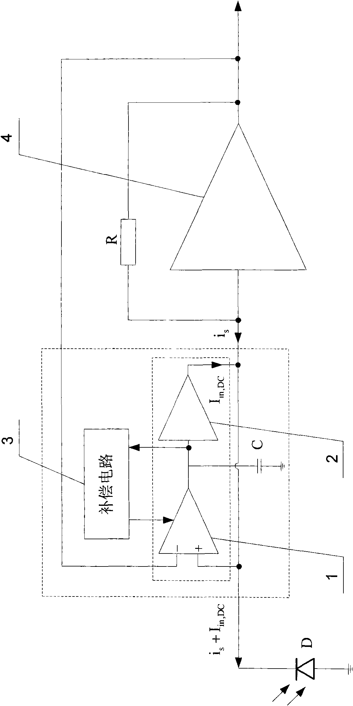
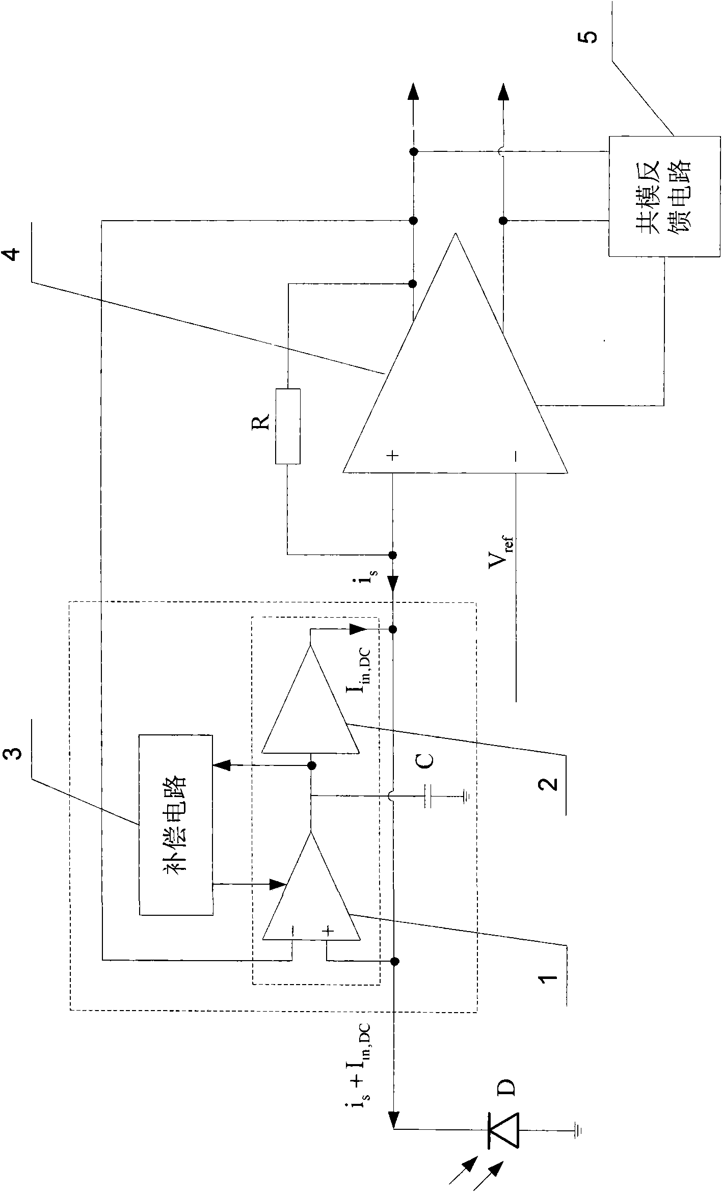
[0010] Specific implementation mode one: the following combination figure 1 Describe this embodiment, this embodiment comprises gyrator, compensation circuit 3 and capacitor C, gyrator comprises first transconductance operational amplifier 1 and second transconductance operational amplifier 2, the output end of first transconductance operational amplifier 1 is connected with the first transconductance operational amplifier 1 The input terminals of the two transconductance operational amplifiers 2 are connected, and the output terminal of the first transconductance operational amplifier 1 is connected with one end of the capacitor C, and the other end of the capacitor C is grounded. The output terminal of the first transconductance operational amplifier 1 and the connection point lead-out line of the input terminal of the second transconductance operational amplifier 2 are also connected with the input terminal of the compensation circuit 3, and the output terminal of the compen...

specific Embodiment approach 2

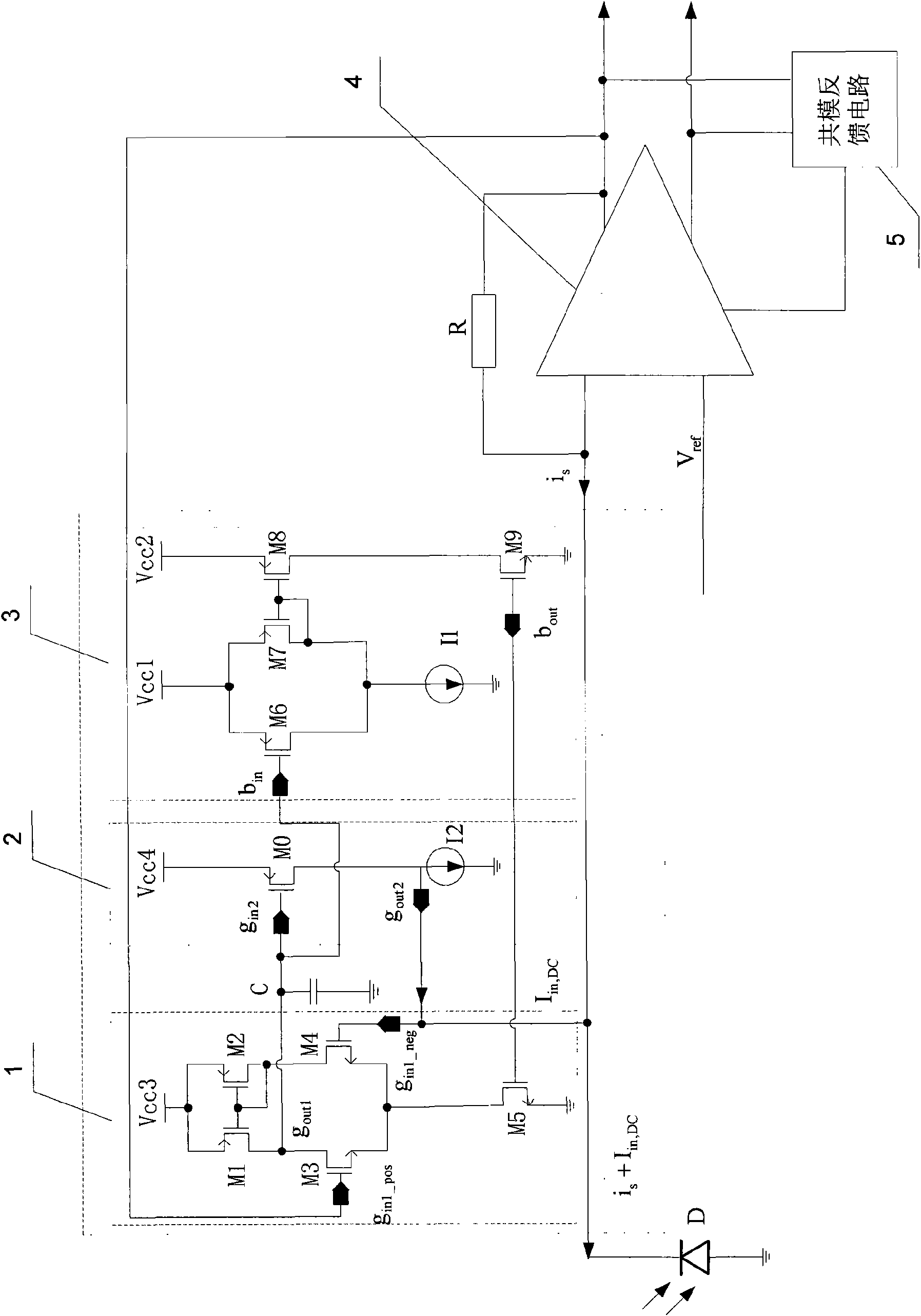
[0012] Specific implementation mode two: the following combination Figure 2 to Figure 8 This embodiment is described. The difference between this embodiment and the first embodiment is that the compensation circuit 3 includes a sixth MOS transistor M6, a seventh MOS transistor M7, an eighth MOS transistor M8, a ninth MOS transistor M9 and a first current source I1, the source of the sixth MOS transistor M6 is connected to the source of the seventh MOS transistor M7 and connected to the first power supply Vcc1, the drain of the sixth MOS transistor M6 is connected to the drain of the seventh MOS transistor M7 and connected to the first current The positive pole of the source I1 is connected, the negative pole of the first current source I1 is grounded, the gate of the seventh MOS transistor M7 is connected to the drain of the seventh MOS transistor M7, and the gate of the seventh MOS transistor M7 is also connected to the drain of the eighth MOS transistor M8. The gate is conn...


PUM


Abstract

A DC interference suppressor circuit used for transimpedance preamplifier of infrared receiving system belongs to the field of circuit design. The aim of the invention is to settle a problem of inferior suppression effect of transimpedance preamplifier of infrared receiving system to DC interference. The gyrator of the invention comprises two operational transconductance amplifiers. The output end of first operational transconductance amplifier is connected with the input end of second operational transconductance amplifier. The connection point leading-out wire of two operational transconductance amplifiers is connected with one end of capacitor C. The other end of capacitor C is grounded. The connection point leading-out wire of two operational transconductance amplifiers is also connected with the input end of compensating circuit. The output end of compensating circuit is connected with a bias voltage signal input end of first operational transconductance amplifier. The output end of second operational transconductance amplifier is connected with the non-inverting input end of first operational transconductance amplifier and is taken as one end of DC interference suppressor circuit. The non-inverting input end of first operational transconductance amplifier is taken as the other end of DC interference suppressor circuit.

Description

technical field [0001] The invention relates to a direct current interference suppression circuit used for a transimpedance preamplifier of an infrared receiving system, belonging to the field of circuit design. Background technique [0002] Infrared technology has the advantages of small size, low power consumption, low cost, stable performance, and no need to apply for a specific frequency license. Therefore, with the rapid development of infrared technology and the integrated circuit industry, more and more fields and products Infrared technology is used as the main way of remote control or data transmission. Because infrared remote control technology is especially suitable for remote control of electrical appliances used indoors, it can prevent interference between control lines in different rooms; and because of its small size and low power consumption, it is also used in portable electronic products and high-end electronic toys. a wide range of applications. However,...

Claims


Application Information

Patent Timeline
IPC IPC(8): H04B15/00H03K19/0185H03F3/45H04B10/06
Inventor 喻明艳王永生徐丽来逢昌李景虎
Owner HARBIN INST OF TECH
Why Eureka
Try Eureka