
Wire harness

A wire harness and grounding rod technology, applied in the field of wire harnesses, can solve the problems of reduced shielding effect, damage, and inability to shield the overall uniformity, and achieve the effect of increasing the contact area

Inactive Publication Date: 2009-09-23
PHOETON CORP
View PDF1 Cites 35 Cited by
  • Summary
  • Abstract
  • Description
  • Claims
  • Application Information

AI Technical Summary

Problems solved by technology

As a result, it is impossible to make the entire shield body have a good uniform potential, and there is a problem that the effect of shielding is reduced.
In addition, if the shield is melted by laser welding, it will cause damage to the inner dielectric layer between the shield and the core wire

Method used


Image

  • Wire harness
  • Wire harness
  • Wire harness

Examples


Embodiment Construction

[0019] Hereinafter, embodiments of the present invention (hereinafter referred to as embodiments) will be described with reference to the drawings.

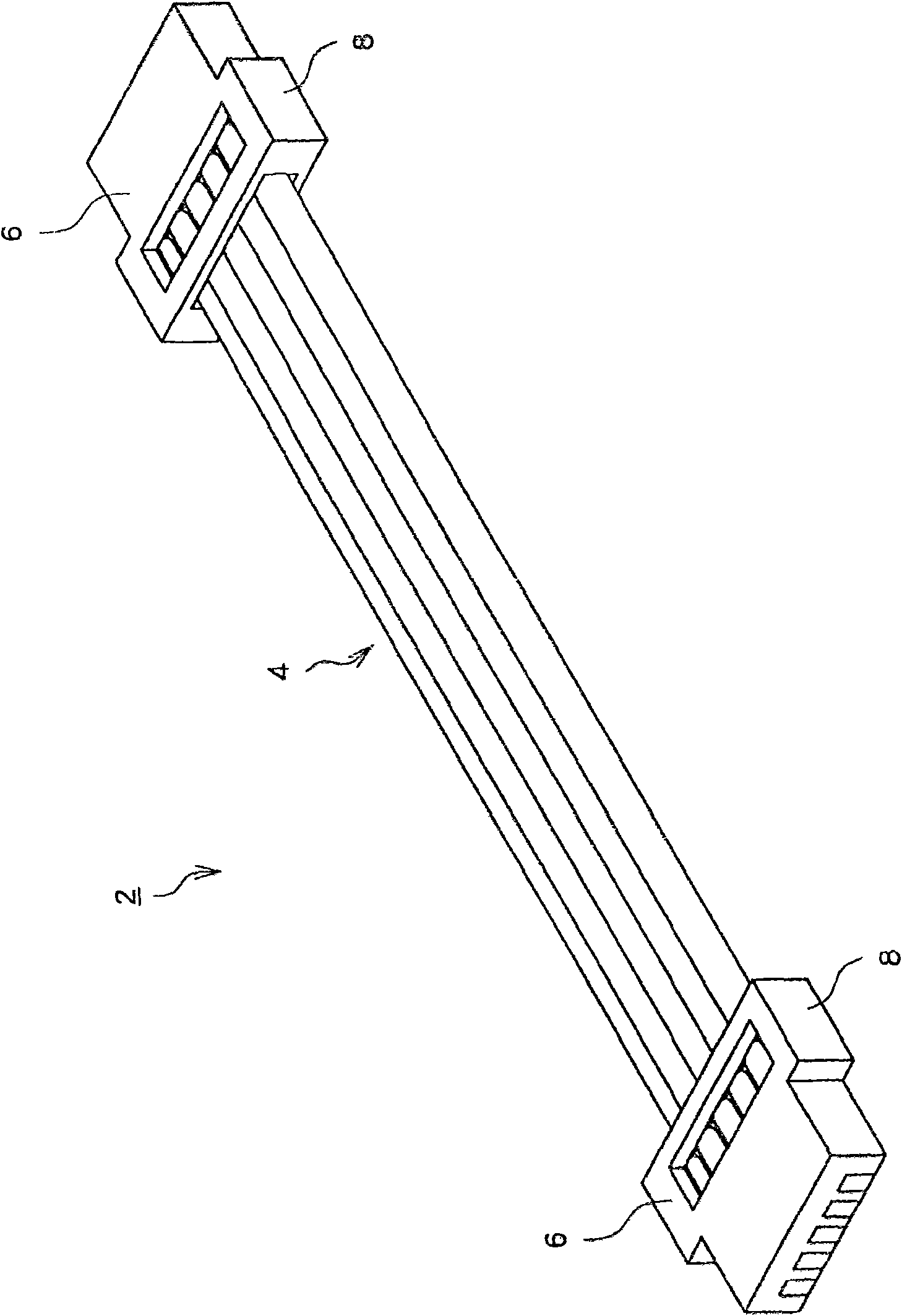
[0020] figure 1 It is a schematic perspective view of the wire harness of embodiment. The wire harness 2 is composed of a cable part 4 and connector parts 6 respectively provided at both ends. The cable unit 4 is, for example, a flat cable composed of a plurality of coaxial cables arranged in parallel. The shape of the connector part 6 is determined by the housing 8, for example, what constitutes a male connector is called a plug housing, and what constitutes a female connector is called a socket housing. E.g, figure 1 The illustrated connector portion 6 is a male connector, and is fitted to a female connector mounted on a board or the like (not shown).

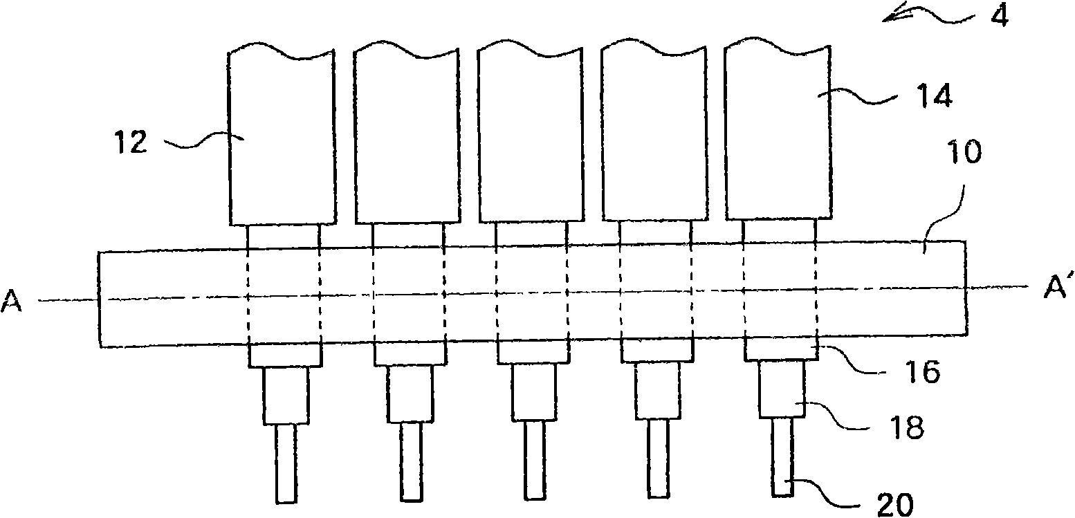
[0021] figure 2 It is a schematic diagram which shows the structure of the connector part 6. The connector part 6 includes a housing 8 , a ground rod 10 , and an end part...


PUM


Abstract

A wire harness using a coaxial cable, in which a ground bar and the shield of the coaxial cable are connected at a connection section in an environmentally friendly process and in a manner providing the harness with good electric characteristics. The ground bar (10) is made of a material having a lower melting point than the shield (16). For example, the ground bar (10) is made of brass or aluminum having a lower melting point than copper that forms the shield (16). The ground bar (10) and the shield (16) are connected together by applying a laser beam to the ground bar (10) and laser bonding them together by spots (30). Since the shield (16) has a higher melting point than the ground bar (10), melting of the shield (16) is suppressed because of the use of the laser bonding and, further, thermal damage to an inner dielectric layer under the shield (16) is suppressed. The environment is less affected because solder is not used.

Description

technical field [0001] The present invention relates to a wire harness having a coaxial cable and a connector (terminal part), and more particularly to a connection structure between a ground bar in the connector and a shield (outer conductor part) of the coaxial cable. Background technique [0002] Wire harnesses are used inside automobiles and various electronic devices to electrically connect parts and boards. Especially in information equipment such as mobile phones and personal computers, wire harnesses using coaxial cables are used for high-speed transmission of high-capacity signals. In addition, for miniaturization and high-density assembly, for example, so-called AWG#42 is used for the coaxial cables. of extremely thin lines. [0003] The wire harness is connected between connectors, for example, by a flat cable in which a plurality of coaxial cables of extremely thin wires are arranged at narrow intervals. A connector for connecting such a plurality of coaxial ca...

Claims


Application Information

Patent Timeline
IPC IPC(8): H01B11/20H01B7/00H01B11/18H01R24/02
CPCH01R9/0524H01R9/0792H01R43/0221H01R12/598H01B11/18H01B11/20
Inventor 榆孝儿玉康司仓田忠
Owner PHOETON CORP
Learn More