
Sputtering device

A sputtering device and substrate technology, applied in the direction of sputtering coating, vacuum evaporation coating, coating, etc., can solve the problems of uneven quality of aluminum film, increase of upper particle size, etc.

Pending Publication Date: 2022-05-13
ULVAC INC
View PDF7 Cites 0 Cited by
  • Summary
  • Abstract
  • Description
  • Claims
  • Application Information

AI Technical Summary

Problems solved by technology

The applicant found that in this way, gases such as water molecules or oxygen molecules adsorbed thereon will be released from the surface of the first baffle part, and the released gas is easily absorbed by the outer edge of the substrate to be processed near the first opening. Capture, in addition to this, since the outer edge portion of the processed substrate located near the first opening is locally heated, the grain size locally increases on the outer edge portion of the processed substrate, which leads to uneven film quality of the aluminum film

Method used


Image

  • Sputtering device
  • Sputtering device
  • Sputtering device

Examples


Embodiment Construction

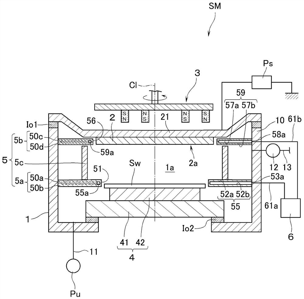
[0017] Referring to the accompanying drawings, an embodiment of the sputtering device of the present invention will be described by taking the case where a silicon wafer (hereinafter referred to as "substrate Sw") having a substantially circular outline is used as a substrate to be processed and an aluminum film is formed on the surface of the substrate Sw as an example. . The following terms denoting such directions as up and down are preceded by figure 1 The shown installation posture of the sputtering apparatus is a reference.

[0018] refer to figure 1 , SM is a sputtering device, and the sputtering device SM has a vacuum chamber 1 . An exhaust pipe 11 is connected to the vacuum chamber 1, and the vacuum in the vacuum chamber 1 is exhausted to a prescribed pressure (such as 1 × 10 -5 Pa), the exhaust pipe 11 shown communicates with a vacuum pump unit Pu composed of a turbomolecular pump or a rotary pump or the like. The side wall 10 of the vacuum chamber 1 is connected...


PUM


Abstract

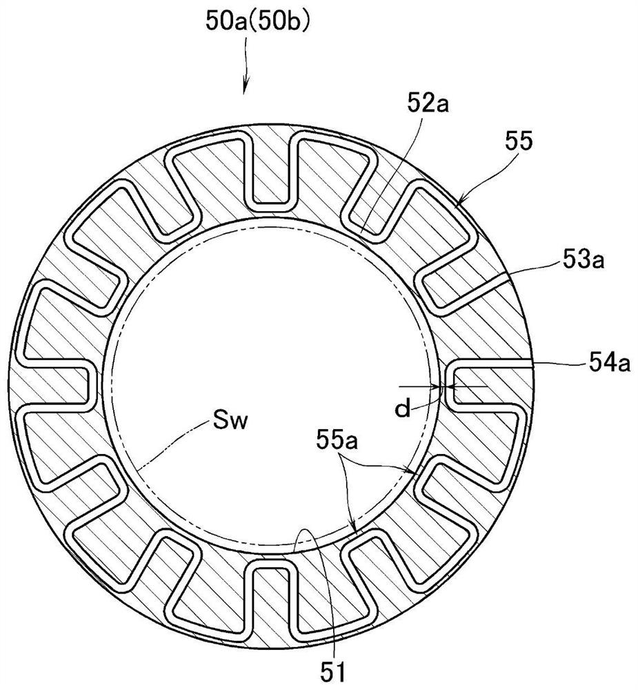
The present invention provides a sputtering apparatus capable of suppressing local temperature rise at an outer edge portion of a substrate to be processed. This sputtering device (SM) is provided with: a vacuum chamber in which a target (2) and a substrate (Sw) to be processed are disposed facing each other; and a baffle plate (5) surrounding a film formation space (1a) between the target and the substrate to be processed in the vacuum chamber. The sputtering apparatus is provided with a cooling unit for cooling the baffle plate, the baffle plate has a first baffle plate part (5a) disposed around the substrate to be processed and having a first opening (51) for facing the substrate to be processed to the film formation space, the first opening having the same profile as the substrate to be processed, and the cooling unit has a first refrigerant channel (55) for cooling the first baffle plate part (5a) and a second refrigerant channel (55) for cooling the first baffle plate part (5a). And a second baffle portion (55a) disposed on the first baffle portion and having a channel portion (55a) extending to a portion of the first baffle portion located around the first opening.

Description

technical field [0001] The present invention relates to a sputtering apparatus including: a vacuum chamber in which a target and a substrate to be processed are arranged facing each other; and a baffle that surrounds a film-forming space between the target and the substrate to be processed in the vacuum chamber. Background technique [0002] Such a sputtering device is known in Patent Document 1, for example. The sputtering device is composed of a first baffle part (lower part), a second baffle part (upper part) and an intermediate baffle part (cylindrical body), wherein the first baffle part (lower part) It is arranged around the substrate to be processed, and has a first opening, the first opening makes the substrate to be processed face the film forming space, and has the same outline as the substrate to be processed; the second baffle part (upper part) It is arranged around the target and has a second opening, the second opening makes the target face the film-forming sp...

Claims


Application Information

Patent Timeline
Patent Type & Authority Applications(China)
IPC IPC(8): C23C14/35C23C14/34
CPCC23C14/35C23C14/34H01J37/3441C23C14/564C23C14/541C23C14/3407C23C14/56
Inventor 铃木康司长岛英人田代征仁
Owner ULVAC INC
Learn More